A while back I wrote a blog series for Atmel on how to build a microcontroller board.
I also created a version for my blog, and it became very popular.
The idea was to show what it takes to build a microcontroller board from scratch.
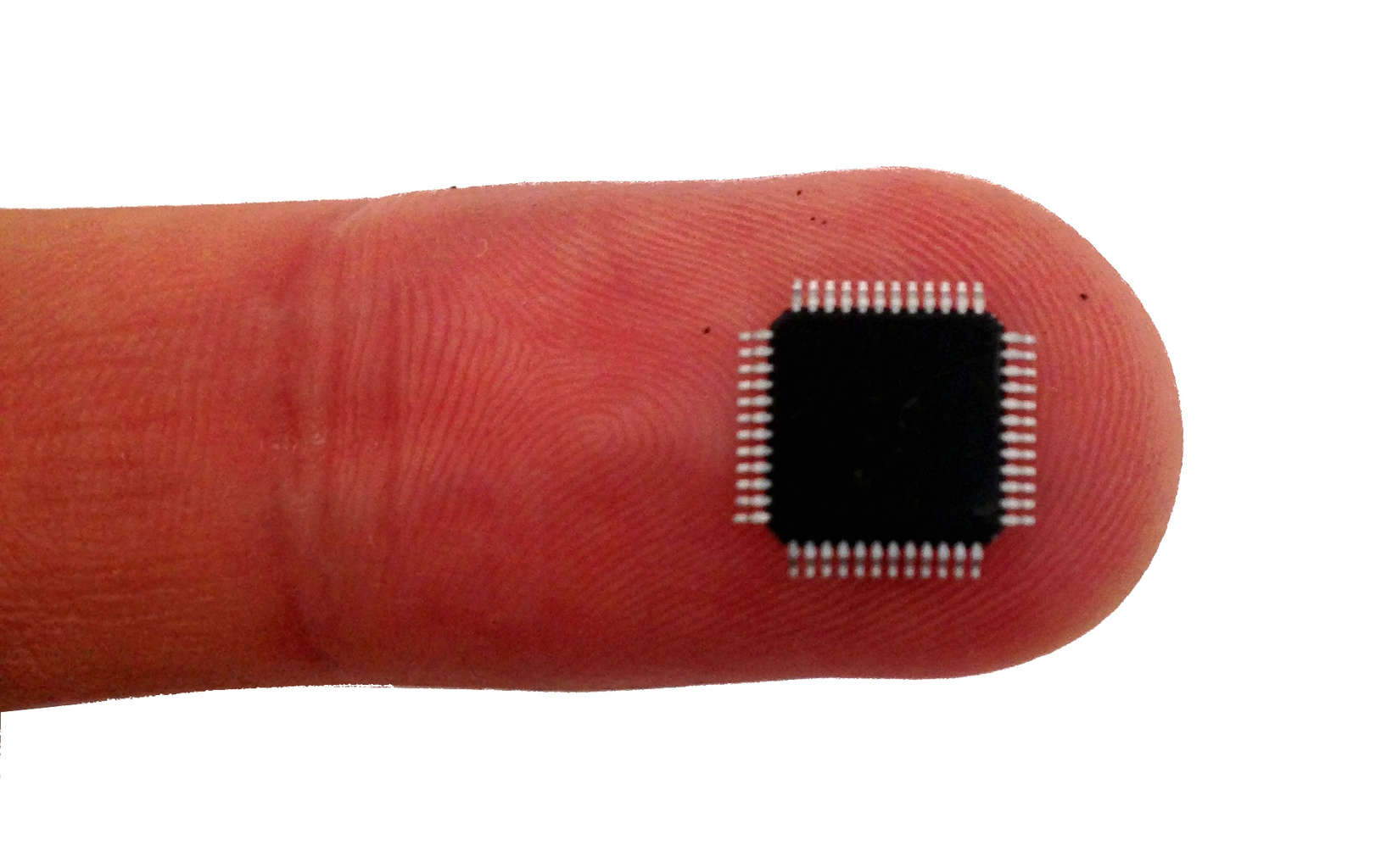
Microcontrollers are components that make it easy to control things like LEDs, motors, or fans based on sensor input like temperature, light, or speed.
Since it’s easy to make advanced functions with microcontrollers, almost all things electronic use a microcontroller these days.
To use a microcontroller in your project you need to learn to write code. And you need to learn how to upload that code onto the chip. I highly recommend Arduino as a starting point. It makes coding and uploading much simpler.
This page is a library resource with tutorials and the basics of microcontrollers.
A while back I wrote a blog series for Atmel on how to build a microcontroller board.
I also created a version for my blog, and it became very popular.
The idea was to show what it takes to build a microcontroller board from scratch.

To complete today’s part of the microcontroller tutorial – I have doubted myself, I’ve burned my finger and I’ve received a surprise bill from the customs.
But all in all, I’m very happy with the result. I made it work. And I love the feeling I get when I make something work!
We are now at part 5, the final part, of the microcontroller tutorial. Up until now we have learned:
 Let’s get ready to circuit board desiiiiiiiiign!
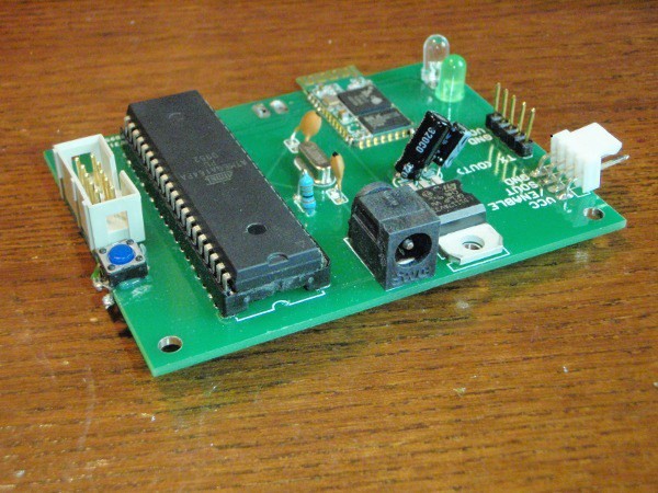
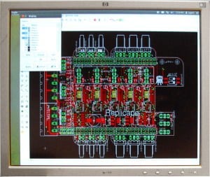
We are now in the fourth part of the microcontroller tutorial. We have a microcontroller circuit diagram ready. It’s time to make a circuit board. I love this part. This is the “magical” step that takes the idea we started with and turns it into something real.
In this tutorial I will teach you how to build your own microcontroller circuit. This way, you can easily add microcontrollers to your own projects. We are now at part three of this tutorial.
In part one of the microcontroller tutorial, we looked at what a microcontroller is. We saw that a microcontroller is like a small computer, and that you can use it to build amazing things like cell phones or even your own handheld game-console.
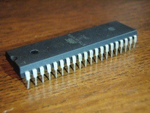
Then in part two, we looked at different types of microcontrollers, and we chose one for our purpose. We chose the ATmega32U2 because we can program it through USB and it is reasonably easy to solder at home.
In this third part of the microcontroller tutorial, we are going to design our circuit from scratch. So we need to design a schematic diagram with all the components and connections necessary to make our circuit work.
Let’s build this thing!
In the previous part of the microcontroller tutorial series, we looked into the basics of microcontrollers.
Our goal is to build a microcontroller circuit that is as simple as possible. So that we can make it at home.
Next up in this tutorial is choosing a microcontroller. This can be hard! At least if you don’t know what you are doing. But after reading this second part, it will become easy ;)
 This is my first of five posts in this microcontroller tutorial series. Throughout this tutorial, I will be building a microcontroller circuit while documenting the process. By following what I do, you can make your own at home.
My goal is to make a circuit that is as simple as possible, and which requires no external programmers or debuggers. You should be able to just plug it into a USB port on your computer and program it.
I have not planned this out in any way. I am just going to build it, and write about the process. Hopefully we’ll end up with a usable circuit.
When I first started learning about microcontrollers, I found them really intriguing. The thought of being able to write code to control electronics was so cool! But what is a microcontroller?
At that time I had already started playing around with programming. And with the microcontroller, I saw that I would be able to interact with the real world through programming! I was intrigued indeed.
But even though I was very enthusiastic about the microcontroller, I didn’t start using it until years later. The thing was, it seemed so complicated to use. I realize now that if I had invested just a little bit of time to learn about it, I would have been able to work with it.
But instead I waited several years before I actually took the leap and started using it…
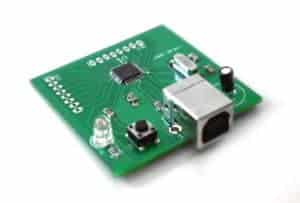
Using a USB circuit is the most common method for communicating between devices and computers.

In the old days usually people used the parallel port or the serial port. But these ports are becoming more and more rare. And on laptops they are almost non-existent.
But all computers have USB ports.
Yeah, and USB stands for Universal Serial Bus just in case you didn’t know ;)
 Using a microcontroller board is a simple way to get started using microcontrollers in your projects. You will get a development board with a microcontroller and all the components needed to make it work.
This means you can focus on your idea instead of the details around setting up a microcontroller circuit.
And usually the schematic diagram is provided so that you can easily incorporate the microcontroller in your own circuit later on.
I often use a microcontroller board when I want to test a new microcontroller. Or when I want to make a prototype.
I wanted to write a little bit about some of the boards I have used.
Microcontroller programming can seem a bit tricky because there are many confusing choices to make. I remember how I felt in the beginning. With all the available compilers, IDE’s, programmers and programming methods – no wonder you get confused!
So, let’s break it down.

I struggled a lot when I was learning the microcontroller basics. I followed different tutorials and ended up with lots of different software on my computer, which made it confusing. And I had to use an external board for programming the chip.
All of this made it hard to understand what I actually needed to make it work.
So to make microcontroller programming as simple as possible for you – here is an overview of what you need to do.
I loved learning about the microcontroller basics when I was studying. It meant I could start taking advantage of microcontrollers in my electronics projects. It kind of felt like with this knowledge, I was unstoppable. I could build ANYTHING!
And it is actually true. Microcontrollers are powerful components. They let you write programs to control your electronics. Combine this knowledge with how to build your own circuit boards, and you’re gonna make amazing things.
By using a microcontroller in your project you will have access to a vast amount of functionality from the tips of your (programming) fingers.