In this 555 Timer tutorial, you’ll learn how to use the 555 timer to do fun things.
One of the first things many do with it is to create a blinking light. But that’s just one simple example of the many things you can do with this chip. You can also control motors, create an alarm, create a musical instrument, and much more.
Let’s start with an overview of the pins.
555 Timer Pinout
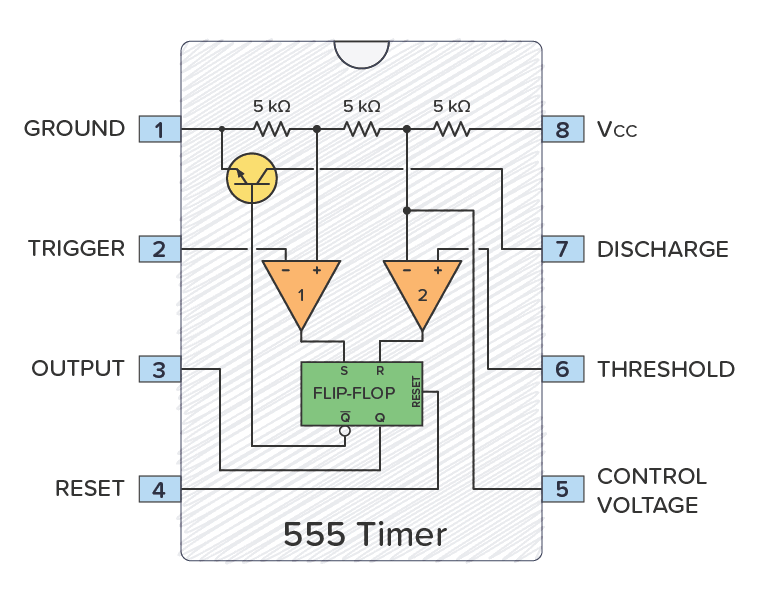
Pin 1 Ground
This pin connects to the negative side of the battery.
Pin 2 Trigger
When this pin goes low (less than one-third of VCC), the output goes high.
Pin 3 Output
The output voltage from the chip is around 1.5 V lower than VCC when high and around 0 V when low. A 555 timer can give out only 100 to 200 mA in total. Check your chip’s datasheet for the exact value.
Pin 4 Reset
This pin resets the whole circuit. It’s an “inverted” pin, which means it resets when the pin goes low. This means the pin must be high normally so that the chip isn’t in a “reset” state.
Pin 5 Control Voltage
This pin is used to control the threshold voltage of the Threshold pin. This can be useful when you want to adjust the frequency of the circuit without changing the values of R1, R2, and C1. Sometimes you’ll see this pin connected with a capacitor (0.01 µF/10 nF) to ground; this is a way to keep any noise on it from influencing the frequency. Sometimes you’ll see it disconnected.
Get the 555 Timer Cheatsheet
A super helpful reference that makes it easy to design circuits, so that you can build oscillators, timer circuits, and more in no time.
Note: I’ve heard from people not able to get their circuit working without this capacitor. So you can try adding a capacitor between this pin and ground if your circuit is not working.
Pin 6 Threshold
This pin sets the output back to low when the voltage goes high (above two-thirds of VCC).
Pin 7 Discharge
This pin is unconnected when output is high, and it’s connected to ground when output is low.
Pin 8 VCC Supply
This is the positive power supply pin and can take a voltage between 5 and 15 V.
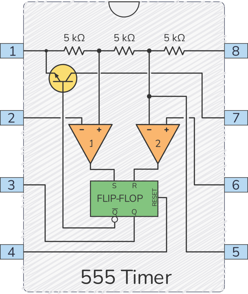
To learn more about the circuit on the inside, check out the article How Does a 555 Timer Work?
Astable Mode
When the 555 Timer is in astable mode it means that the output will never be stable. The output will keep switching between HIGH and LOW forever. That means it works as an oscillator.
You can use this to blink a light, create sound, control motors, and much more!
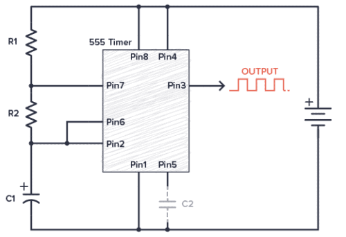
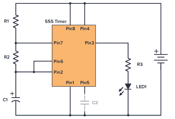
555 Timer Astable Circuit Example
Our first example is how to blink an LED with the 555 Timer. This is like the “hello world” equivalent of this IC.
Component List
This circuit is simple enough to build on a breadboard. To build it, you need the following components:
- 9V Battery
- 555 Timer IC
- R1-R3: Resistor, 1 kΩ
- LED1: Red 5mm LED or similar
- C1: Capacitor, 1000 µF
- C2: Capacitor, 10 nF (it usually works without this)
You don’t need exact values for the resistors and capacitors. But if you use the values listed above, your LED should blink about once every other second. Use the 555 Timer calculator to find the blinking frequency for other values.
Monostable Mode
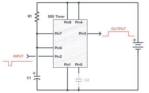
Monostable means the output is stable in one state, and it will always come back to this state. You can push it out of that state, but it will always return back to its stable state after a certain time.
The output from the 555 Timer in monostable mode is normally LOW. When you trigger the circuit, the output goes HIGH for a certain amount of time before it goes back to LOW again.
This is sometimes called a one-shot circuit.
The time it stays HIGH is decided by the size of a resistor and a capacitor. The higher the values, the longer it stays HIGH.
If you connect a buzzer to the output, you can create an alarm circuit that is triggered for example by a window being opened.
555 Timer One-Shot Example Circuit
The following circuit turns on an LED when you push the button. After about 10 seconds, the LED turns off.

Component List
- 9V Battery
- 555 Timer IC
- R1: Resistor, 100 kΩ
- R2: Resistor, 5kΩ to 1 MΩ (this is a pull-up resistor)
- R3: Resistor, 1 kΩ
- LED1: Red 5mm LED or similar
- C1: Capacitor, 100 µF
- C2: Capacitor, 10 nF
- S1: Pushbutton, normally open
For longer delays, increase C1 and/or R1. If you want an adjustable delay, replace R1 with a potentiometer. Use the 555 Timer calculator to find the values you need.
The output is connected to control an LED, but could easily be modified to control a motor, a lamp, a coffee maker, or anything else. Just replace R3 and the LED with a transistor. See how in the section Driving Higher Loads below.
Bistable (Flip-Flop) Mode
Bistable means the output is stable in both states (HIGH and LOW). It will stay in one state until you push it over to the other state. Then it stays in the other state. You push it from one state to the other with the Trigger and Threshold pins.
This mode isn’t a timer function at all, and it’s not a common way to use the 555 Timer. In this mode, the 555 Timer works as a flip-flop.
You can for example use it to reverse the direction of a robot when it bumps into a wall. Or separate the ON and OFF switches for a machine.
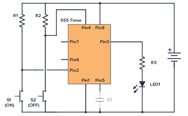
555 Timer Bistable Example Circuit
The following example shows the 555 Timer in bistable mode. Here you have separate ON and OFF buttons to control an LED.
Component List
- 9V Battery
- 555 Timer IC
- S1, S2: Pushbutton, normally open
- R1, R2: Resistor, 5kΩ to 1 MΩ (these are pullup resistors)
- Resistor (R3): 1 kΩ
- LED: Red 5mm LED or similar
- Capacitor (C1): 10 nF
The output is connected to control an LED, but could easily be modified to control a motor, a lamp, or anything else by connecting a transistor. See the section Driving Higher Loads below for examples.
555 Timer Output Current
The output of the 555 Timer can sink and source current of up to 200 mA.
Sourcing is when the output is HIGH and you’ve connected something from the output down to ground:
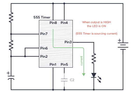
In the above circuit, the LED turns on when the output is HIGH.
Sinking is when the output is LOW and you’ve connected something from VCC to the output:
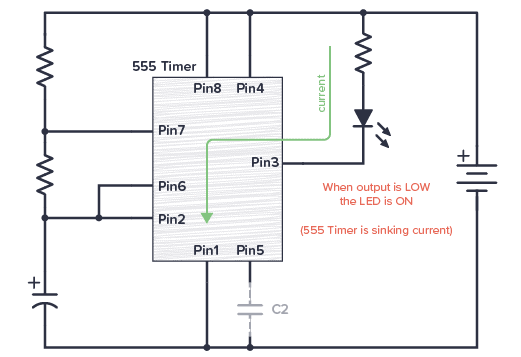
In the above circuit, the LED turns on when the output is LOW.
If you use both sourcing and sinking in your circuit, you can make a cool emergency vehicle light effect by connecting two LEDs; a blue one that is sourcing current and a red one that is sinking current.
Or how about connecting two buzzers with different frequencies to create a siren?
Circuit Example: Police Car Emergency Lights
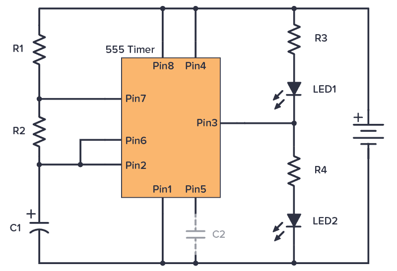
Component List
- 9V Battery
- 555 Timer IC
- R1-R2: Resistor, 1 kΩ
- R3: Resistor, 470 Ω
- R4: Resistor, 330 Ω
- LED1: Red LED
- LED2: Blue LED
- C1: Capacitor, 1000 µF
- C2: Capacitor, 10 nF (it usually works without this)
R1, R2, and C1 control the blinking speed. R3 and R4 set the brightness of the LEDs.
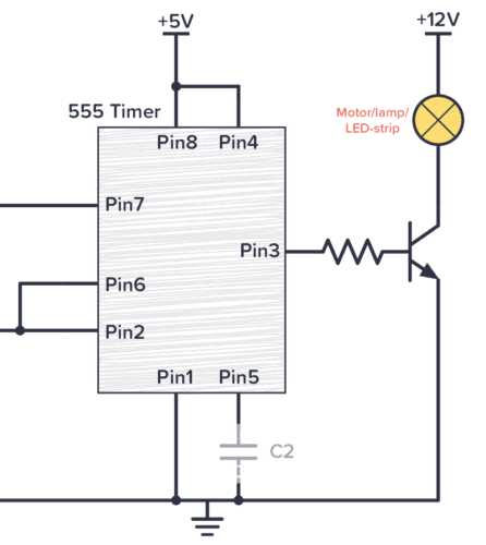
Driving Higher Loads
If you want to control motors, LED strips, or other things that need more than 200 mA of current, you can connect a transistor to the output.
If you want to use an NPN transistor, you’ll need to connect a resistor between the output and the base to limit the base current. 1 kΩ will probably work fine as a starting point.
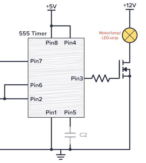
If you want to use a MOSFET on the output, make sure you use a MOSFET with a VGS that is lower than the output voltage from your 555 timer.
The resistor is there to protect the output pin from high spikes of current when the MOSFET is being turned on. But given that the 555 Timer supports 200 mA, it will most likely work without it in most cases.
555 Timer Datasheet
Looking for the datasheet for the 555 timer? Each manufacturer has their own. Here’s a list of a few of the most common ones:
- LM555 datasheet by Texas Instruments
- NA555/NE555/SA555/SE555 datasheet by Texas instruments
- NE555 datasheet by Diodes Inc
- LM555C datasheet by National Semiconductor
More 555 Timer Tutorials
Get the 555 Timer Cheatsheet
A super helpful reference that makes it easy to design circuits, so that you can build oscillators, timer circuits, and more in no time.
I am not quite sure about the following diagram
555 Timer with MOSFET transistor on output
Driving higher loads from a 555 Timer with an MOSFET transistor
I think that this diagram is just a section of a complete diagram.
Can you show me a complete diagram that has a push-button that will allow
a laser pointer to shine light on a photoresistor for about 15 seconds?
Please send the diagram to my email address, if possible.
Thank you very much.
Hello. I love this post. A great idea I think. As I am a beginner and a school student (of 6th grade), sometimes I face troublesome situations. this helped me to manage my problems with timers. can you make a post about making a traffic light circuit?
I’ll keep it in mind for the future!
I’m wanting to build a simple circuit using the 555 tmer that will turn on an LED solid for a set amount of time (5 mins) when power is turned on and then after that time is up, to start flashing until the circuit is powered off. I don’t know if this could be done using one 555 timer or whether it would require two timers such as a 556.
I would appreciate any help you could give me on this.
Thanks
Hi Matt, you would need two 555 timers to do this (or one 556). One in monostable mode that gives you the 5 minute delay, then one in stable mode that turns on after the 5 minutes to blink the LED.
I have a question. I want to make a standard box fan go on and off every 2-3 minutes for an art project I’m building. Will a 555 work for that?
Yes, it will. You might need a transistor on the output if it’s a big fan, but other than that it should be straight forward.
I would like to build a senseative audible continuity checker
Where as if probes are held in fingers a very low frequency can be heard. This sound would increase in frequency with less resistance between pobes. All the way up to high pitch squeal when shorted together. Hopefully a 9v power supply in a small cigarette pack size box.
Sounds cool!
Your comment about the Pin 5 control pin sometimes needing a 10nF capacitor may have saved my ass on a hobby project I’ve been working on. I’ve been using a 555 timer as a soft latch circuit for a pushbutton and it needs to be stable over long periods of time and only toggle when I want to toggle it by pushing the button. My design has worked MOST of the time, but it loses its latch at the most random times. I’ve put a piece of paper down on my desk, and the 555 timer lost it’s latch. I’ve sat down at my desk, and it’s lost its latch. It happens in the most random of times and I’ve never been able to reproduce the issue after it happens. I had left pin 5 floating on my design, and I guess a control pin flapping in the wind does stupid stuff… I just slapped a 10nf cap on it and I think this may have been the fix. So far so good. Thanks again m8.
So yeah like you said, your circuit may work without a cap on pin 5, but it may not be stable. It may be stable for hours at a time, and you may only have a couple problems a week with it, but it’ll probably have problems. Slap that cap on there for peace of mind.
I’m trying to circuit bend a toy drum to be a rhythm machine. the problem is once you push a button the toy play the beat for 10 seconds then stops. Would a 555 timer work as a trigger to keep the beat going?
Yes, you could set it up to “push” the button repeatedly if that would work? The you need to set it up in astable mode.
I want to use a 555 to run a stepper motor very slowly. The 555 will just send a pulse to a stepper motor controller to step the motor one step. It looks like a pulse will only be needed about every 5 minutes.
This is for a polar aligned camera mount which will track the stars.
If the 555 would work for this, could you please point me in the direction for me to learn how to do it? Thank you very much
Hey Darwin, Yes you can use the 555 timer for that. Just set it up in astable mode as explained in this article. You can find which values to use from our 555 calculator: https://www.build-electronic-circuits.com/circuit-calculator-conversion/555-timer-calculator/
I have built the monostable (with a 2N3904 transistor) and it works fine with only an LED as the load. But when I connect the intended load (an electromagnet taking 150ma) it is on all the time. Do you have a suggestion?
Thanks
Hi,
I am trying to make a circuit where the output is contact closure when triggered. Can you please help me on this
Hi. Great article, thaksf for that. I’m relatively new designing electronic circuits. I’d like to try my hand at building a superhet radio receiver circuit. Can a 555 in astable mode be used in place of a crystal oscillator or would the thermal characteristics of the 555 result in too much of a frequency drift to be used for that purpose?
I’m actually not sure. I came across this AM radio article where a 555 timer has been used, so it’s possible to use it for radio: https://hackaday.com/2011/02/25/hear-that-its-a-555-timer-am-radio/
I’m not very educated on electronics but am competent at soldering and following directions. I want to put LED cornering lights on my truck. Each side will illuminate when I turn that sides blinker on. Would a 555 timer work by sensing the pulsing signal from the blinker in turn lighting the cornering LED and then when the blinker clicks off the LED would turn off as well? If my description works, would I use a timer for either side for a total of 2? I would also use this to trigger a relay that will power the LED cornering lights. Can you give me a specific wiring plan and any part numbers for parts? Thank you for your time!
I’ve an idea, but not confident to progress it. I want a circuit to be triggered by a +12v (actually one of two 12v inputs), which triggers an audible buzz/beep out to a headphone jack. I’ve got as far as working out that the IC555 is likely the starting point.
Ultimately, this will feed a bluetooth transmitter, but that will likely be just an off-the-shelf with jack plug input. Hence the requirement for the headphone jack as the output.
Any help, advice, diagrams, or other options would be appreciated.
Hi Rob,
Yes, the 12V signal could turn on a 555 Timer in astable mode. The simplest way is to use the 12V signal as the power source for the 555 Timer (if the 12V signal is able to supply enough current). Use components that set the frequency into the audible range, maybe around 1000 Hz, and connect that to your headphone jack output.
Best,
Oyvind
Hi Oyvind
Thanks for the quick reply. So if I use the “555 Timer Astable Circuit Example”, but replace R3 with a connection to the base of an NPN transistor (such as 2N2222A), the connector of the NPN to a 10kΩ resistor and a 10nF capacitor, and swap LED1 for a headphone jack output? Connect the other side of the jack to ground, and the NPN emitter to ground as well?
I’m repeating my interpretation of Copilot AI suggestions, and your suggestion. If you could confirm if this sounds about right?
What would I need do if I wanted it to be triggered from either of two 12v sources? The 12v supplies currently light a bulb and so I’m assuming will provide enough current for this. I just don’t want to connect both supplies as I don’t want one triggering this, and therefore lighting the second bulb.