The 555 Timer Reaction Game is a simple and fun project that tests your reflexes. Using the classic 555 timer IC in conjunction with a CD4026 decade counter with 7-segment output, you can create a game that challenges players to press a button as quickly as possible after a signal starts.
Player 1 uses the Start button to begin the count, and Player 2 hits the Stop button to freeze the display. The player’s reaction time is indicated by the number on the display; lower numbers signify quicker reactions.
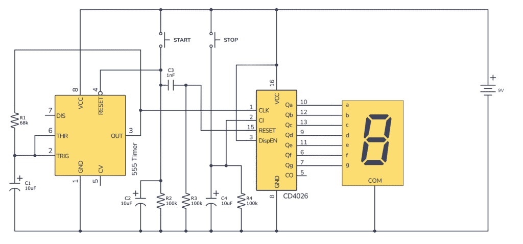
The Circuit
Parts List
1 × 9V Battery
1 × 555 Timer IC
1 × CD4026 IC
1 × 7-segment display
1 × Resistor, 68 kΩ (R1)
2 × Resistor, 100 kΩ (R2, R3, & R4)
2 × Capacitor, 10 µF (C1, C2 & C4)
1 × Capacitor, 1 nF (C3)
2 × Push-button switch (Start and Stop)
Note: When you connect the outputs from the CD4026 directly to the 7-segment LEDs, you are pushing the current limits of the CD4026. You might damage the IC if you keep it connected over a period of time. To avoid this, add a 470 Ω resistor in series for each LED segment.
How the 555 Timer Reaction Game Works
The 555 timer is set up in an astable mode, continuously outputting clock pulses at a frequency set by resistor R1 and capacitor C2. The CD4026 counts these pulses and updates the display accordingly.
When Player 1 presses the Start button, the counter begins counting pulses from the 555 timer, displayed on the 7-segment display. The counting speed is sufficiently rapid that the individual numbers are not easily observed with the naked eye.
As soon as Player 2 presses the Stop button, the counting stops and the last value remains on the 7-segment display.
How To Build This Project On a Breadboard
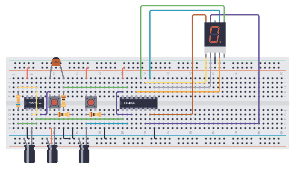
Begin by placing the 555 Timer IC and the CD4026 IC on the breadboard, ensuring they are spaced out with enough room for other connections.
Get the 555 Timer Cheatsheet
A super helpful reference that makes it easy to design circuits, so that you can build oscillators, timer circuits, and more in no time.
Connect the VCC (pin 16) and GND (pin 8) of CD4026 to the positive rail and ground rail respectively on the breadboard.
Carefully place the 7-segment display ensuring that the correct pins are connected to the corresponding output pins on the CD4026.
Wire the 555 timer in astable mode as shown in the schematic, then attach the Start and Stop buttons to the respective Reset (pin 4 of 555 timer) and Clock Inhibit (pin 2 of 4026 IC) pins.
Make sure all connections match the schematic before connecting the battery. When you’re done, pressing the Start button should start the counter and increment the display rapidly. Pressing Stop should stop the counting.
Troubleshooting Tips
- If the display is not counting, check that the 555 timer is oscillating by verifying the output on pin 3 with an oscilloscope or a multimeter set to frequency measurement.
- Make sure the push-button switches are correctly wired and function as intended. Improperly connected switches can prevent the game from starting or stopping.
- If the numbers on the display are erratic or not advancing properly, examine the connections between the CD4026 and the display for any errors or loose connections.
- Verify that capacitors C1, C2, and C4 are correctly placed according to polarity, as reversing them might prevent the circuit from working as expected.
More 555 Timer Tutorials
Get the 555 Timer Cheatsheet
A super helpful reference that makes it easy to design circuits, so that you can build oscillators, timer circuits, and more in no time.