The 555 timer IC is a versatile component that can be used in various circuits, including a metronome. A metronome is a device used by musicians to keep a steady tempo during practice. In this tutorial, you’ll learn how to build a simple metronome using the 555 timer IC.
Parts List
- 1 × 9V Battery
- 1 × 555 Timer IC
- 1 × Potentiometer, VR1 250kΩ
- 1 × Resistor, R1 1kΩ
- 2 × Capacitor, C1 & C2 22µF
- 1 × Speaker, 8Ω
The Circuit
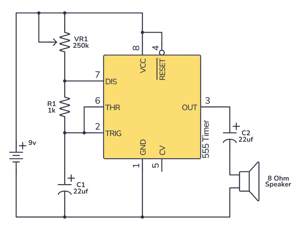
The 555 timer is configured in astable mode, meaning it generates a continuous sequence of pulses. The frequency of these pulses determines the tempo of the metronome.
- Timing Components: The resistors (VR1 and R1) and capacitor (C1) determine the pulse interval, which can be adjusted by changing the resistance of VR1.
- Capacitor Discharge: The output toggles between high and low states, causing C2 to charge and discharge, which in turn creates the sound in the speaker.
- Speaker Output: When the output pin (pin 3) is high, C2 charges through the speaker, creating a click sound.
How To Build The 555 Metronome on a Breadboard
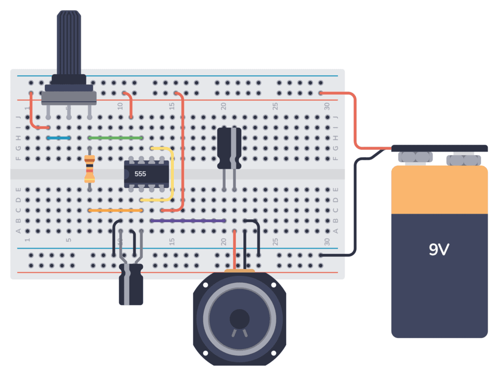
Connect the 555 timer’s pin 8 (VCC) to the positive supply column, and pin 1 (GND) to the negative supply column. And connect pin 4 (RESET) to pin 8 (VCC) to avoid resetting the timer.
Use a wire to connect pin 6 (THR) to pin 2 (TRIG).
Place VR1 and R1 in series between pin 8 (VCC) and pin 7 (DIS). Then connect pin 7 (DIS) to pin 6 (THR), forming a loop with the series resistors and the timer.
Connect C1’s positive lead to the junction between VR1 and R1, and its negative lead to pin 1 (GND). Connect C2’s positive lead to pin 3 (OUT) and its negative lead to one terminal of the speaker. Finally, connect the other terminal of the speaker to pin 1 (GND).
Optionally, attach pin 5 (CV) to ground through a small 10nF capacitor to stabilize the frequency (not shown in the schematic).
Carefully check all connections against the schematic to ensure they match before you connect the battery. Incorrect wiring can lead to the circuit not functioning properly or even damage the 555 timer.
Get the 555 Timer Cheatsheet
A super helpful reference that makes it easy to design circuits, so that you can build oscillators, timer circuits, and more in no time.
Turn on the power to the circuit. Adjust VR1 to change the rate of the metronome click. You should hear a regular click through the speaker that corresponds to the tempo set by VR1.
Troubleshooting Tips
- If there is no sound, check the speaker and the connections to pin 3.
- Ensure that the polarity of the electrolytic capacitors is correct; reversing them may damage the components.
- If the tempo is not changing when adjusting VR1, double-check the connections between VR1, R1, and the timer.
You now have a functional electronic metronome. The tempo can be adjusted using the potentiometer, allowing for a range of speeds suitable for various musical practices.
More 555 Timer Tutorials
Get the 555 Timer Cheatsheet
A super helpful reference that makes it easy to design circuits, so that you can build oscillators, timer circuits, and more in no time.
