This 555 Timer Police Lights circuit is an interesting electronics project that simulates the alternating flash of police vehicle lights using LEDs.
The circuit uses a 555 timer IC and a CD4017 decade counter to create the flashing effect. By adjusting the frequency of the 555 timer, you can control how quickly the LEDs flash, mimicking the strobe light effect found on emergency vehicles.
The Circuit
You can build this circuit using a 555 timer, a 4017 IC, some diodes, LEDs, resistors, transistors, and a capacitor.
Parts List
1 × Battery, 9V
1 × 555 Timer IC
1 × CD4017 Decade Counter IC
2 × BC547 NPN Transistor
1 × Capacitor, 2.2µF
6 × Diode, 1N4148
2 × LED, Red
2 × LED, Blue
1 × Resistor, 1kΩ (R1)
1 × Resistor, 22kΩ (R2)
2 × Resistor, 4.7kΩ (R3, R4)
6 × Resistor, 470Ω (R5, R6, R7, R8, R9, R10)
How It Works
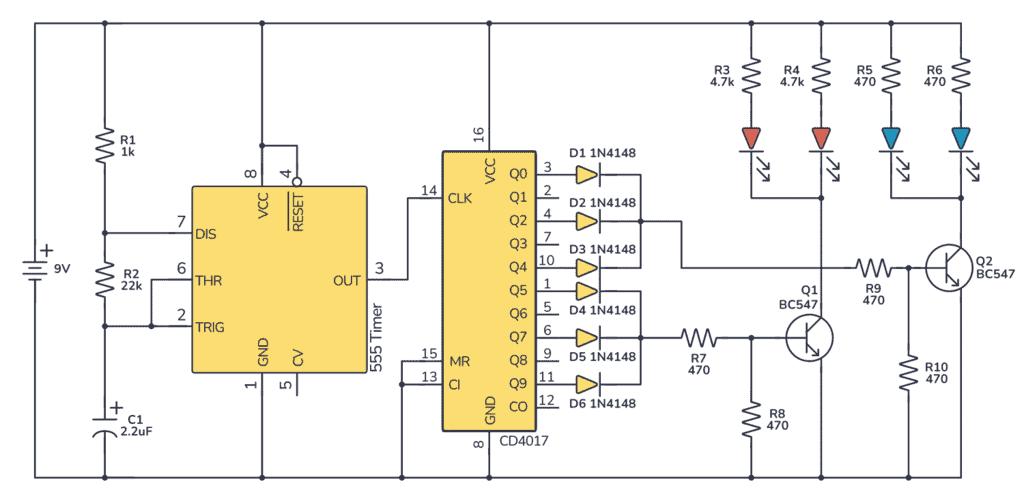
The 555 Timer is configured in astable mode, producing a clock pulse that is fed into the clock input of the CD4017 decade counter. Each time the 555 outputs a pulse, the CD4017 advances its count and turns on the next sequential output.
The outputs (Q0-Q5) from the CD4017 are connected through the diodes to the base of the two BC547 transistors, in such a way that red LEDs flash three times in succession and then blue LEDs flash three times in succession. The diodes control the flow of current, allowing specific transistors to activate only certain LEDs.
Transistors Q1 and Q2 are used to drive the red and blue LEDs, respectively, amplifying the current coming from the CD4017 outputs to a level that can power the LEDs. The 4.7 kΩ and 470 Ω resistors limit the current to the LEDs, protecting them from burning out due to excessive current.
Since blue LEDs need more current, 470Ω was used for the blue LEDs.
Build Something Useful This Evening
This gadget lets you use any IR remote-control to control your lamp, garden lights, heater oven, garage door, or anything else.
How To Build The 555 Timer Police Lights on a Breadboard
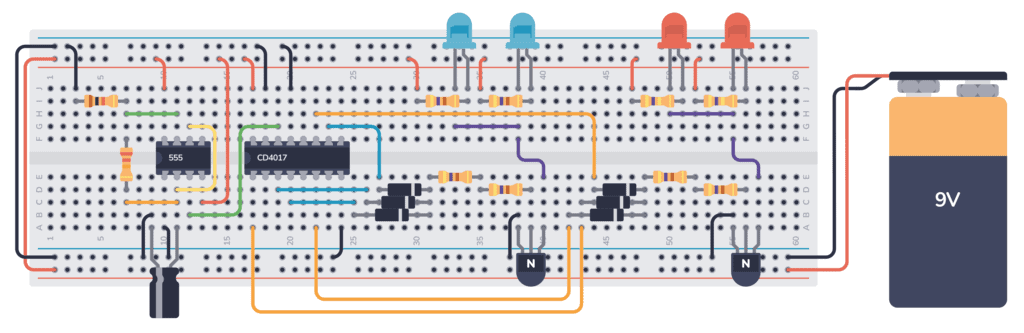
Start by placing the 555 Timer IC and CD4017 IC on the breadboard with an appropriate distance between them for easy connections.
Connect the VCC (pin 8 of the 555 timer and pin 16 of the CD4017) and GND (pin 1 of the 555 timer and pin 8 of the CD4017) to the positive and ground rails of the breadboard.
Connect the RESET (pin 4 of the 555 timer) to the positive rail, and connect MR and CI (pins 15 and 13 of the 4017 IC) to the ground rail.
Place the transistors on the breadboard and connect their collectors to the 9V supply through the corresponding LEDs and resistors.
Wire the 555 Timer IC as shown in the schematic, using the R1, R2, and C1 to set the time interval of astable oscillation.
Arrange the 1N4148 diodes, according to the schematic, ensuring that the signals from the CD4017 correctly drive the transistors Q1 and Q2. And connect the resistors R7, R8, R9, R10.
Once the circuit is connected, power it up and the red LEDs should flash three times, followed by the blue LEDs flashing three times, repeatedly.
Troubleshooting Tips
- If the LEDs do not flash in the correct order, verify that each diode is placed according to the schematic and oriented correctly, with the anode connected to the CD4017 outputs and the cathode toward the transistor bases.
- Make sure that all the resistors are of the correct value and placed as per the circuit diagram. Incorrect resistor values can cause the LEDs to be too dim or too bright, or potentially damage them.
- If the LEDs are constantly on or do not flash, check for short circuits or incorrectly connected transistors. Transistors should switch on and off in response to the output from the CD4017.
- Ensure the polarity of the capacitor is correct; incorrect polarity can prevent the 555 timer from oscillating.
More 555 Timer Tutorials
Build Something Useful This Evening
This gadget lets you use any IR remote-control to control your lamp, garden lights, heater oven, garage door, or anything else.