Logic gates are the basic building blocks of digital electronics. These are the components that we use for “doing stuff” with the 1s and 0s. You can combine them to create other building blocks like latches, flip-flops, adders, shift registers, and more.
The basic logic gates are AND, NAND, OR, NOR, XOR, XNOR, and NOT.
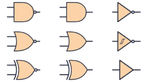
All the gates are pretty easy to understand, and as you’ll see, their names give away what they do. I recommend you read through each gate explanation below, then get yourself some gates and test out how they work by building some test circuits.
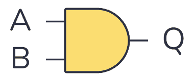
AND gate
The AND gate takes two (or more) inputs and gives out a 1 (HIGH/true) if all the inputs are 1. Otherwise, it gives out a 0 (LOW/false).
The truth table is below, but all you really need to remember is that the AND gate needs a 1 on input A and input B to give out 1. All the logic gates have names that make their functionality, well, logical.
| Input A | Input B | Output Q |
|---|---|---|
| 0 | 0 | 0 |
| 0 | 1 | 0 |
| 1 | 0 | 0 |
| 1 | 1 | 1 |
If you want to use it in a circuit, the IC 4081 contains four AND gates.
NOT gate/Inverter
The simplest logic gate of all is the NOT gate. It takes one bit as input (A). And it gives as an output (Q) what is NOT on the input. So if there is a 1 on the input, its output is 0. And if there is 0 on the input, its output is 1. It’s also called an inverter.

| Input A | Output Q |
|---|---|
| 0 | 1 |
| 1 | 0 |
If you want to use a NOT gate in your circuit, you can for example use the IC 4572 or IC 40106.
Get Our Basic Electronic Components Guide
Learn how the basic electronic components work so that circuit diagrams will start making sense to you.
Is the buffer part of the logic gates?
Note that there is also a component called a buffer that looks like the NOT gate, but without the circle on the output.
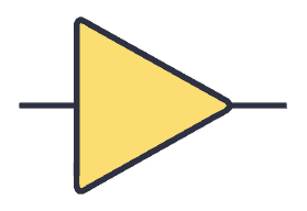
The output from the buffer is the same as the input. So I wouldn’t consider it a part of the logic gates (since it doesn’t do any logical operation). But it’s sometimes included as a logic gate.
The point of the buffer is to add delay into a digital circuit or to add the possibility to pull out more current from a gate that can’t deliver much current.
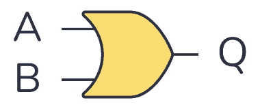
OR gate
The OR gate takes two (or more) inputs and gives out a 1 if any of the inputs are 1. Otherwise, it gives out a 0.
The truth table is below, but all you really need to remember is that the OR gate needs a 1 on input A or input B to give out 1.
| Input A | Input B | Output Q |
|---|---|---|
| 0 | 0 | 0 |
| 0 | 1 | 1 |
| 1 | 0 | 1 |
| 1 | 1 | 1 |
If you want to use it in a circuit, the IC 4071 contains 4 OR gates.
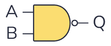
NAND gate
The NAND gate (or NOT AND) operates in the opposite way of the AND gate. It’s like if an AND gate had a NOT gate on its output:
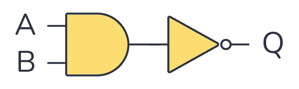
You’ll find the truth table below. But all you need to remember is that the only time the output of a NAND gate is 0 is when both the inputs are 1.
| Input A | Input B | Output Q |
|---|---|---|
| 0 | 0 | 1 |
| 0 | 1 | 1 |
| 1 | 0 | 1 |
| 1 | 1 | 0 |
If you want to use NAND gates in a circuit, the CMOS IC 4011 contains 4 NAND gates.
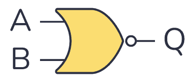
NOR gate
The NOR gate (or NOT OR) operates in the opposite way of the OR gate. It’s as if an OR gate had a NOT gate on its output.
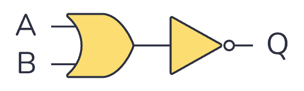
You’ll find the truth table below. But all you need to remember is that the only time the output of a NOR gate is 1 is when both the inputs are 0.
| Input A | Input B | Output Q |
|---|---|---|
| 0 | 0 | 1 |
| 0 | 1 | 0 |
| 1 | 0 | 0 |
| 1 | 1 | 0 |
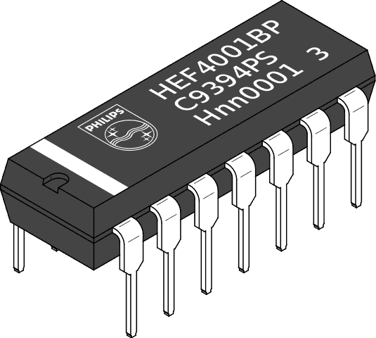
If you want to use NOR gates in a circuit, the IC 4001 contains 4 NOR gates.
XOR gate
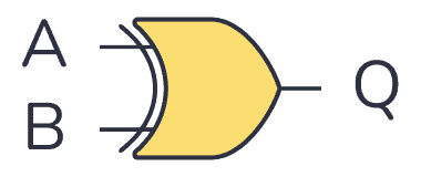
The XOR gate (or Exclusive OR) outputs 1 if one of its two inputs is 1 – but not both. You can also look at it this way – if the two inputs are different from each other, the output is true.
| Input A | Input B | Output Q |
|---|---|---|
| 0 | 0 | 0 |
| 0 | 1 | 1 |
| 1 | 0 | 1 |
| 1 | 1 | 0 |
If you want to use XOR gates in a circuit, the IC 4070 contains 4 XOR gates.
XNOR gate
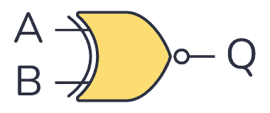
The XNOR gate (or Exclusive NOT OR) works like an XOR gate with an inverter on the output. Another way to look at it is to notice that the output becomes 1 if its two inputs are equal – either two 1s or two 0s.
| Input A | Input B | Output Q |
|---|---|---|
| 0 | 0 | 1 |
| 0 | 1 | 0 |
| 1 | 0 | 0 |
| 1 | 1 | 1 |
If you want to use XNOR gates in a circuit, you’ll find four of them in the IC 4077.
Using Logic Gates in Circuits
A logic gate can be built with transistors and usually comes as an Integrated Circuit (IC).
There are two classic IC series where you’ll find all the logic gates; The 7400-series and the 4000-series. Both series contain chips with similar functions.
The 7400 series is the oldest series. The 4000 series was introduced as a lower-power and more versatile option to the 7400. But today, several families of the 7400-series exist, some with similar properties as the 4000-series.
Check out my reference library of common ICs with pinouts, explanations, and example circuits:
List of 4000 Series IC
List of 7400 Series IC
More Logic Gates Tutorials
10 Simple Steps to Learn Electronics
Electronics is easy when you know what to focus on and what to ignore. Learn what "the basics" really is and how to learn it fast.
