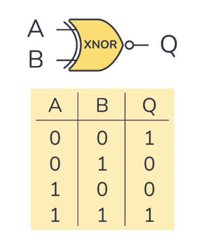
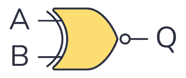
An XNOR gate is a logic gate where the output goes HIGH (or “1”) only if both its inputs are equal. So if the inputs A and B are both HIGH or both LOW, the output Q will be HIGH.
The logic or Boolean expression for an XNOR gate is  which means that:
If A and B are the same, then Q is true
Truth Table
XNOR gates commonly only have two inputs. It will only give out a HIGH or logic “1” if both its inputs are equal. So the inputs must both be HIGH or both be LOW for the output to become HIGH.
XNOR Gate Truth Table
| Input A | Input B | Output Q |
|---|---|---|
| 0 | 0 | 1 |
| 0 | 1 | 0 |
| 1 | 0 | 0 |
| 1 | 1 | 1 |
IC Alternatives with XNOR Gates
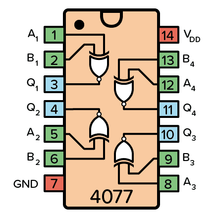
If you want to experiment and build circuits with XNOR gates, you’ll find them in both the 4000 IC series and the 7400 IC series:
- 4077: Four XNOR gates
- 74HC266: Four XNOR gates (HC is the family, can also be LS/HCT/…)
These should all be available as hobbyist-friendly through-hole chips. Just make sure you buy the DIP package version.
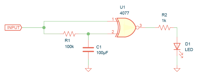
Example Circuit: XNOR Gate Edge Detection
This circuit detects if a signal is going from LOW to HIGH or from HIGH to LOW. The Light-Emitting Diode (LED) on the output turns on for a short amount of time when an edge is detected.
For fast-switching signals, you’d need lower values for R1 and C1, and the LED would be ON for such a short time that it wouldn’t make sense. But instead, it would make sense to for example read the output into a microcontroller, or use a counter to count the edges.

Oyvind's Circuit Tips
Get my tips for learning electronics, curious circuits, useful tutorials, hints for choosing components and much more via email.
More Logic Gates Tutorials

10 Simple Steps to Learn Electronics
Electronics is easy when you know what to focus on and what to ignore. Learn what "the basics" really is and how to learn it fast.