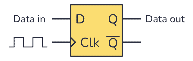
The D Flip-Flop is an edge-triggered circuit that combines a pair of D latches to store one bit. It is commonly used as a basic building block in digital electronics to create counters or memory blocks such as shift registers.
In this tutorial, you will learn how it works, its truth table, and how to build one with logic gates.
What is a Flip-Flop?
Latches and flip-flops are sometimes grouped together since they both can store one bit (1 or 0) on their outputs. In contrast to latches, flip-flops are synchronous circuits that need a clock signal (Clk). The D Flip-Flop will only store a new value from the D input when the clock goes from 0 to 1 (rising edge) or 1 to 0 (falling edge).
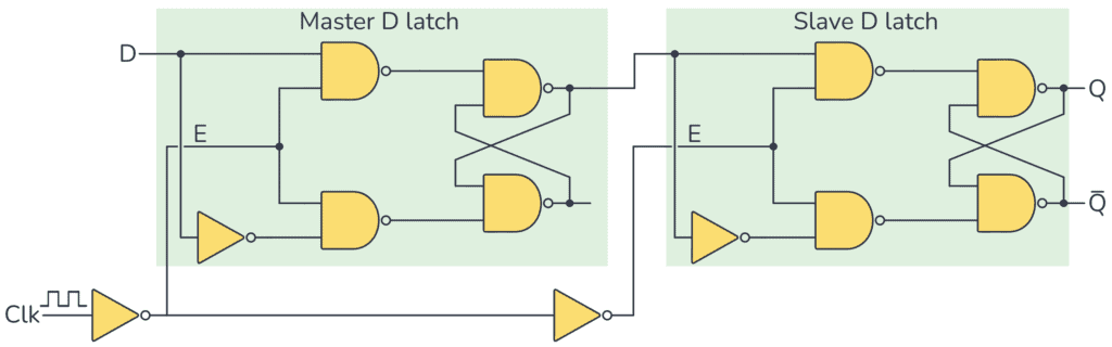
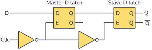
A D Flip-Flop is built from two D latches. You can see a D Flip-Flop that updates on the rising edge below:
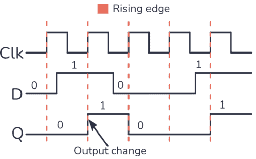
The timing diagram for this circuit is shown below. It shows how a rising edge-triggered D Flip-Flop behaves. The output Q only changes to the value the D input has at the moment the clock goes from 0 to 1.
How Does the D Flip-Flop Work?
Since the output Q only changes when the Clock input goes from 0 to 1, you’ll get the following truth table:
| Clk | D | Q | Description |
|---|---|---|---|
| 0 | X | Q | Memory (no change) |
| 0→1 (↑) | 0 | 0 | Reset Q to 0 |
| 0→1 (↑) | 1 | 1 | Set Q to 1 |
| 1 | X | Q | Memory (no change) |
In the first and last rows of the truth table, the clock input is 0 and 1. None of them is a rising edge signal, so nothing happens. The Q output keeps whatever value it had. In this case, no matter what value the D input has, the Q output won’t change, it will keep its value as it is. This is how this circuit “remembers” a bit.
Have a look at the two middle rows. Here the clock input is going from 0 to 1, so you have a rising edge. This means that if the D input is 0, the Q output will be reset to 0. If the D input is 1, the Q output will be set to 1.
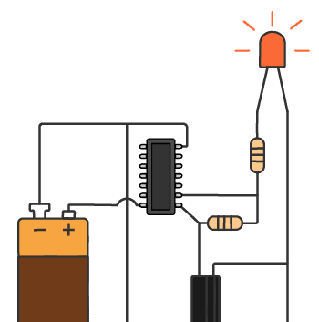
Free Course: Blinking a Light
Join my free email course on how to build a circuit that blinks a light. Enter your details below and you'll receive the first lesson right away:
Presetting
D Flip-Flops that you find in chips ready for use, such as the CD4013, usually also have Set and Reset inputs that you can use to force the D flip-flop into starting with a 1 or a 0 on the output. Using these pins is sometimes referred to as “presetting” the D flip-flop.
The Advantage of a D Flip-Flop vs Latch
One of the downsides of the D latch is that its output can change at any time while its Enable pin is 1. So if you apply a clock signal to the D Latch, the Q output could also change during the time the positive pulse lasts.

In the timing diagram above, you can see that during one clock cycle, the output is both 1 and 0 because the D input changes during the clock pulse. That’s something you don’t want to happen in a clocked digital system.
To get this flip-flop to change its output only on the rising edges of the clock signal you can build a Master-Slave D Flip-Flop Circuit, which requires a combination of two D latches as follows:
How D Flip-Flops Work
The output from the master latch changes to what the D input has when the Clk input is 0.
If Clk is 0, it means that the Enable input of the slave latch is also 0. So nothing happens with the output of this latch.
But at the moment that Clk goes from 0 to 1 (rising edge), the Enable input of the slave latch is set to 1. That means whatever was on the output of the master latch at the moment Clk went from 0 to 1 is saved to the output of the slave latch.
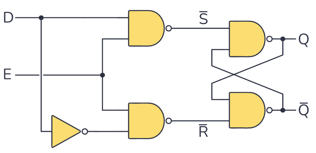
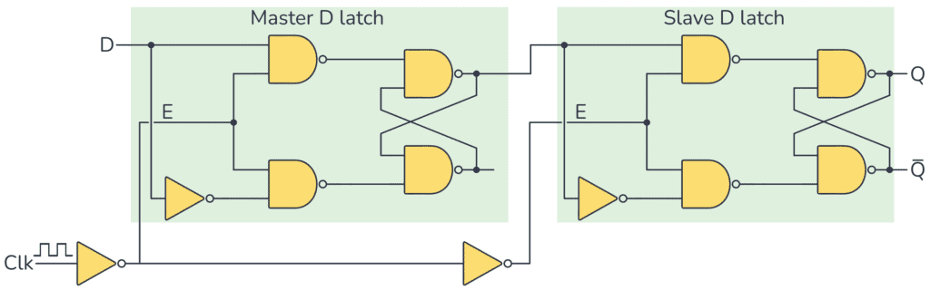
If you substitute the symbols for D latches built with NAND gates you’ll get:
What Can You Use Them For?
The D Flip-flop is a very useful circuit. You can combine several D flip-flops to create for example shift registers and counters, which are used a lot in digital electronics. But you don’t have to build them from scratch. Instead, you can use the CD4013 chip that contains two D flip-flops.
Circuit Example: Shift Registers
To create a shift register, connect the output of one flip-flop to the input of the next. New bits go into the first flip-flop on the left. And for every clock pulse, the bits stored in the other flip-flops are shifted one place to the right.
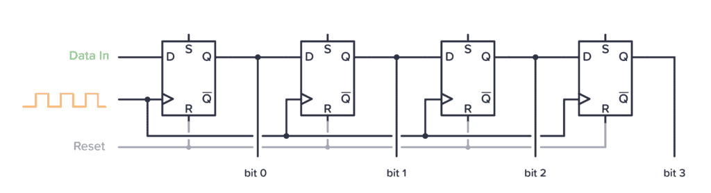
This is useful for example to get more output pins from an Arduino or other microcontroller. To control a shift register, you need one data pin and one clock pin. So with only two pins from the Arduino, you can control as many external pins as you want by using a shift register.
Circuit Example: Ring Counters
If you take the output from the last flip-flop in a shift register and connect it to the input of the first flip-flop, you get a Ring Counter. Preset one of the flip-flops to start with 1, then this 1 will be shifted around and around in the Ring Counter.
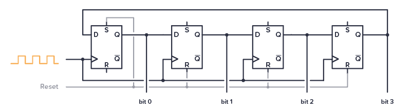
The IC 4017 is a chip with this type of functionality, but with 10 outputs instead of just 4 like above. This makes for a fun chip you can use for example to create the Knight Rider LED bar.
Questions?
Do you have any questions about how the D Flip-Flop works? Let me know in the comments below.
More Digital Electronics Tutorials
Get Our Basic Electronic Components Guide
Learn how the basic electronic components work so that circuit diagrams will start making sense to you.