This is a 555 Timer railroad lights project where two lights are alternating, similar to a railroad crossing signal. The 555 timer is set up in astable mode so that it keeps switching its output between HIGH and LOW, thereby turning on and off the two LEDs connected to the output.
The Circuit
To build this circuit, you’ll need a 555 timer IC, a capacitor, some resistors, and a couple of light-emitting diodes (LEDs).
Parts List
- 555 timer IC
- C1: Capacitor 10µF
- R1: Resistor 47k
- R2: Resistor 470
- LED1 and LED2: Standard LED
How It Works
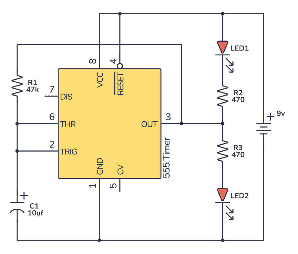
The circuit uses a 555 timer IC to create a blinking effect for two red LEDs, which are often used to simulate the flashing lights at a railway crossing on model train setups. The 555 timer is set up in an ‘astable’ mode, which means it generates a continuous sequence of on-off pulses.
Timing Components: The resistor (R1) and capacitor (C1) determine how fast the LEDs blink. The capacitor charges through R1, and once it reaches a certain voltage, the timer flips its output to turn the LEDs on or off.
LEDs and Resistors: The two LEDs (LED1 and LED2) are connected to the output of the timer through their respective resistors (R2 and R3), which limit the current to prevent the LEDs from burning out. When the 555’s output is high, current flows through the lower LED only and it lights up. When the output is low, current flows through the upper LED only, which turns it on.
When you power up this circuit, the 555 timer repeatedly charges and discharges the capacitor at a rate set by R1 and C1, causing the output pin to alternate between high and low states. This makes the LEDs flash on and off, simulating the warning lights you see at a real railway crossing.
Build The Circuit
Here’s how you can connect this circuit on a breadboard:
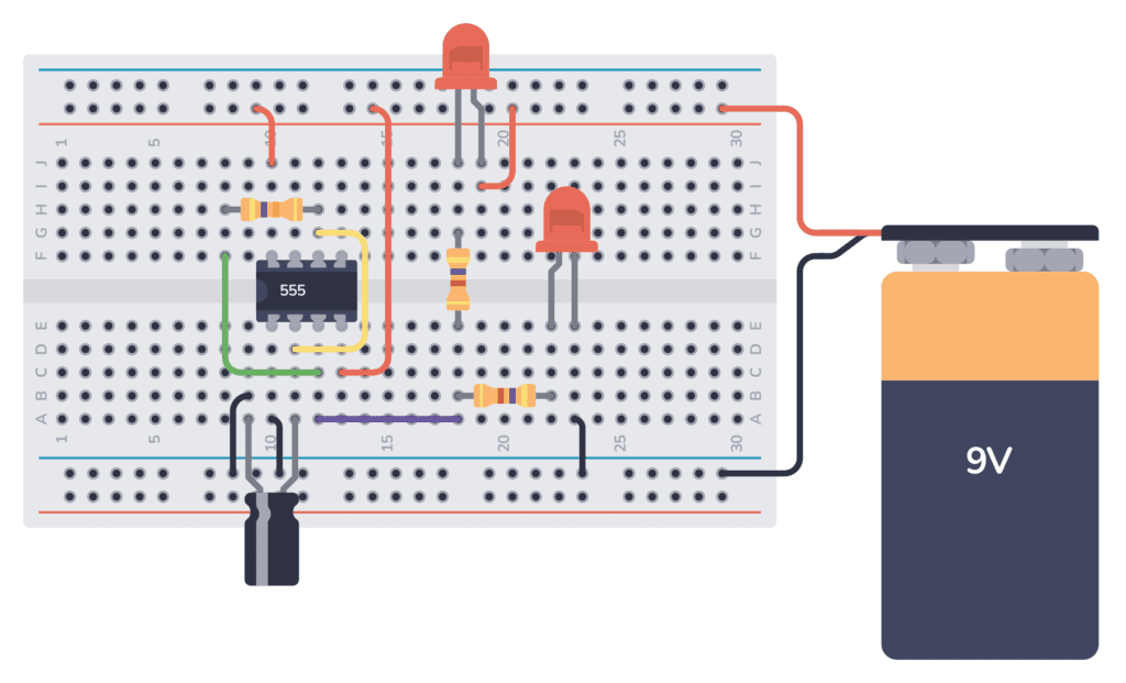
Connect the 9V battery to the power rail and ground rail to turn on the circuit. The 555 Timer Flashing Railroad Lights should start alternating.
Get the 555 Timer Cheatsheet
A super helpful reference that makes it easy to design circuits, so that you can build oscillators, timer circuits, and more in no time.
Always double-check each connection to ensure it matches the schematic before powering the circuit to avoid any shorts or incorrect wiring.
More 555 Timer Tutorials
Get the 555 Timer Cheatsheet
A super helpful reference that makes it easy to design circuits, so that you can build oscillators, timer circuits, and more in no time.