The CD4025 is a CMOS chip with three 3-input NOR gates. Because each gate has three inputs and it has three gates inside, it’s usually called a Triple 3-Input NOR Gate.
A NOR gate is a gate that gives a HIGH output only if non if its inputs are HIGH. It works like a 3-input OR gate with a NOT gate/inverter on the output.
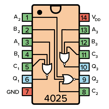
Pin Overview
| Pin Name | Pin # | Type | Description |
|---|---|---|---|
| VDD | 14 | Power | Supply Voltage (+3 to +15V) |
| GND | 7 | Power | Ground (0V) |
| A1 to A3 | 1, 3, 13 | Input | Inputs A of the three NOR gates |
| B1 to B3 | 2, 4, 12 | Input | Inputs B of the three NOR gates |
| C1 to C3 | 5, 8, 11 | Input | Inputs C of the three NOR gates |
| Q1 to Q3 | 6, 9, 10 | Output | Outputs from the three NOR gates |
What is a 3-input NOR gate?
A NOR gate is a logic gate that gives a HIGH output only when all the inputs are LOW as shown in the truth table below.
Therefore, if you input a HIGH in any of the inputs, the output will become LOW. Otherwise, the output will be HIGH.

| Input A | Input B | Input C | Output Q |
|---|---|---|---|
| 0 | 0 | 0 | 1 |
| 0 | 0 | 1 | 0 |
| 0 | 1 | 0 | 0 |
| 0 | 1 | 1 | 0 |
| 1 | 0 | 0 | 0 |
| 1 | 0 | 1 | 0 |
| 1 | 1 | 0 | 0 |
| 1 | 1 | 1 | 0 |
How To Use the CD4025?
First of all, you need a power supply voltage of 3 to 15V. Some versions of the chip support up to 20V. Check the datasheet of your version of the chip for exact values.
To be able to use any of the NOR gates in the chip, you need to first connect the VDD pin to the positive supply terminal and the GND pin to the negative supply terminal.
The A, B, and C pins are the inputs to the three NOR gates in the IC.
The Q pins are the outputs from the NOR gates.
10 Simple Steps to Learn Electronics
Electronics is easy when you know what to focus on and what to ignore. Learn what "the basics" really is and how to learn it fast.
CD4025 Example Circuit – Loop Through RGB LED colors
This circuit will loop through 6 different colors for an RGB LED. The 555 timer creates a clock signal of about 1 Hz. The CD4017 counts the received clock pulses and sets one of six outputs HIGH.
The 3-input NOR gates in the 4025 IC detects which output is high and makes sure the correct colors of the RGB led are turned on.

To build this you’ll need:
- A common cathode RGB LED (D1)
- A 555 Timer (U1)
- CD4017 Decade Counter (U2)
- A chip with three 3-input NOR gates such as the CD4025BE (U3)
- 1 kΩ resistors (R1-R5)
- 470 µF capacitor (C1)
- 10 nF capacitor (C2) – this can often be omitted
Alternatives and Equivalents for CD4025
You likely find the 4025 IC marked as CD4025, NTE4025, MC14025, HCF4025, TC4025, or HEF4025. Usually with a few extra characters at the end (Ex: CD4025BE).
This has to do with the manufacturer of the chip and the technology used. But the functionality and the pins are the same.
If they don’t have any of these chips in your local electronics store, check out my list of online stores where you can find components and tools for all your electronics projects.
Can’t find the 4025? Then try one of the following IC alternatives with 2-input NOR gates:
- 74HC27: Triple 3-input NOR
4025 Datasheet
Download the PDF datasheet for the IC 4025 here:
CD4025B (Texas Instruments)
CD4025 (SYC Electronica)
Go back to the full overview of the 4000-series integrated circuits
10 Simple Steps to Learn Electronics
Electronics is easy when you know what to focus on and what to ignore. Learn what "the basics" really is and how to learn it fast.