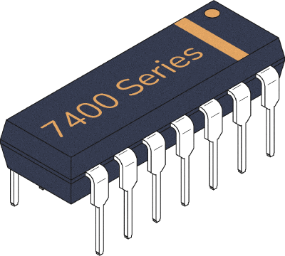
This IC, often found as 74LS00 or 74HC00, is a chip with four basic NAND gates. The NAND gate is a logic gate – one of the most basic building blocks in digital electronics. The chip comes in a 14-pin package with the following pinout:
In this guide, you’re going to learn what the 74×00 IC does and how to hook it up in a circuit.
What does the 74LS00 / 74LS00 do?
The 74×00 gives you four basic NAND gates that can be used individually.
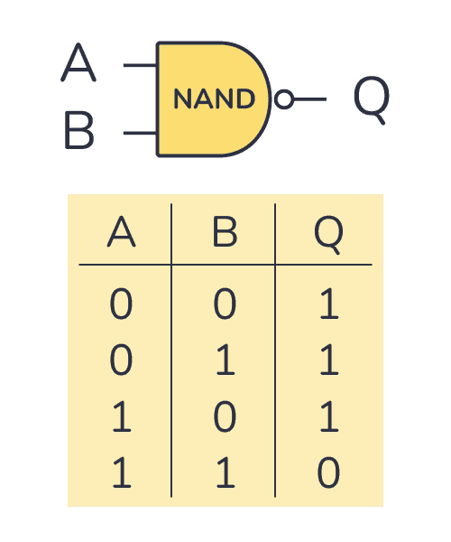
A NAND gate is a logic gate that gives you a 0 (LOW) only if all of its inputs are 1 (HIGH). In the truth table below, you can see what the output will be for any given input:
How To Use This Chip
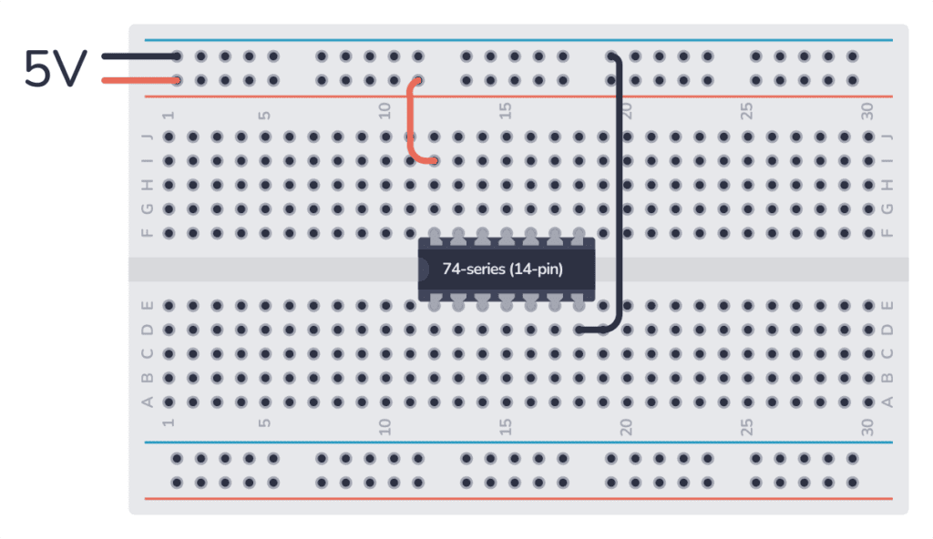
Like every other chip in the 7400 series, this IC must be connected to power before you can use it. Most 7400 ICs support a VCC voltage of 5V. One difference between the HC and LS version of the chip is that the 74HC00 supports 2V to 6V, while the 74LS00 supports only 5V.
Once connected, you can use any of the four basic NAND gates inside.
Output Current
74HC00:
Each gate output of the 74HC00 can sink or source 4 mA when powered with 5V.
74LS00:
HIGH-Level Output Current: 0.4 mA
LOW-Level Output Current: 8 mA
Get the 555 Timer Cheatsheet
A super helpful reference that makes it easy to design circuits, so that you can build oscillators, timer circuits, and more in no time.
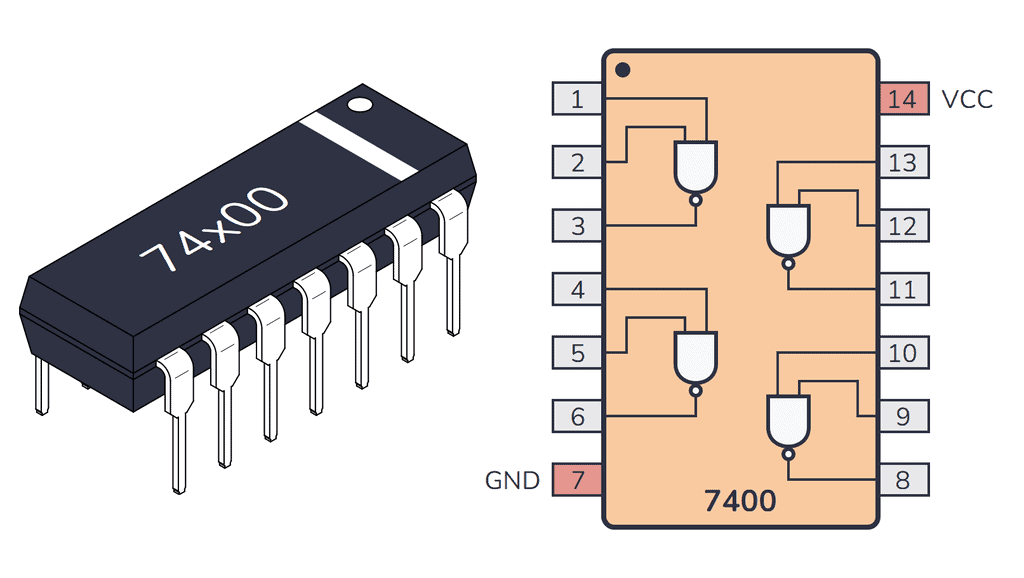
74HC00/74LS00 Pinout
The 74×00 has 14 pins and contains four basic NAND gates, laid out as shown in the pinout diagram below:
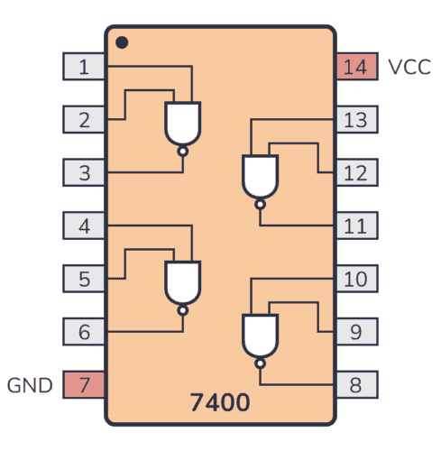
| Pin Name | Pin # | Type | Description |
|---|---|---|---|
| 1A | 1 | Input | Input to the first NAND gate. |
| 1B | 2 | Input | Input to the first NAND gate. |
| 1Y | 3 | Output | Output from the first NAND gate. |
| 2A | 4 | Input | Input to the second NAND gate. |
| 2B | 5 | Input | Input to the second NAND gate. |
| 2Y | 6 | Output | Output from the second NAND gate. |
| GND | 7 | Power | Connect to ground. |
| 3Y | 8 | Output | Output from the third NAND gate. |
| 3A | 9 | Input | Input to the third NAND gate. |
| 3B | 10 | Input | Input to the third NAND gate. |
| 4Y | 11 | Output | Output from the fourth NAND gate. |
| 4A | 12 | Input | Input to the fourth NAND gate. |
| 4B | 13 | Input | Input to the fourth NAND gate. |
| VCC | 14 | Power | Positive power supply. Connect to +5V power. |
74×00 Circuit Example
Here’s a simple project you can build with the 74×00 IC. The two NAND gates make up an SR latch that controls an LED. The LED can be turned on or off with the two buttons.

To build this circuit, you’ll need the following parts:
- 1 x 74×00 (such as 74LS00 or 74HC00)
- 1 x LED (L1)
- 2 x 10 kΩ resistor (R1-R2)
- 1 x 1 kΩ resistor (R3)
- 2 x pushbutton (S1-S2)
Alternatives and Equivalents for 74HC00 / 74LS00
There are many versions of the 74×00 chip. They all have the same functionality, but with different specifications such as supported voltages and maximum current output.
Here’s a list of a few equivalents of this chip:
- 74HC00 (High-speed CMOS)
- 74HCT00 (High-speed CMOS, TTL compatible)
- 74LS00 (High-speed TTL)
- 74LVC00 (Low Voltage TTL)
- 74AC00 (Advanced CMOS)
- 74ALS00 (Advanced Low-Power Schottky TTL)
- 74F00 (Very High Speed)
- 74C00 (CMOS, similar to the 4000-series)
Some manufacturers also add a prefix, such as the SN74HC00 and SN74LS00 by Texas Instruments.
Can’t find the 74×00 anywhere? Then try one of the following IC alternatives:
- 74×03 – Quad 2-input NAND gates (with open-collector outputs).
- 74×132 – Quad 2-input NAND gates (with Schmitt-trigger inputs).
- CD4011 – Quad 2-input NAND gates.
- CD4093 – Quad 2-input NAND gates (with Schmitt-trigger inputs).
If you can’t find the 74×00 IC in your local electronics store, don’t worry, you’ll most likely find it in one of the stores listed on this page of online stores where you’ll find components and tools for all your electronics projects.
Datasheet for the 74LS00 and 74HC00 chips
Download the PDF datasheet for your version of the 74×00 here:
- SN74HC00 (Texas Instruments)
- SN74LS00 (Texas Instruments)
- 74HC00 (Futurlec)
- 74LS00 (Futurlec)
- 74HC00 (Diodes Inc)
10 Simple Steps to Learn Electronics
Electronics is easy when you know what to focus on and what to ignore. Learn what "the basics" really is and how to learn it fast.