Using the transistor as a switch is a practical and useful skill to have. By setting up transistors in very simple circuits, you can easily control things like DC motors, lamps, buzzers, and much more.
This is useful for beginners and experienced electronics enthusiasts alike. In this guide, you’ll learn the basics, the necessary components, and step-by-step instructions for setting up the most common transistors (MOSFET and BJT) as switches.
PS! If you’re completely new to transistors, I recommend you read through How Transistors Work before jumping into this article.
Using Bipolar Junction Transistors (BJTs)
Bipolar junction transistors come in two types, NPN and PNP, and each of these types has three terminals: the base, collector, and emitter. One of the main characteristics of these transistors is that they’re controlled by the amount of current that flows through the base terminal.
BJTs can be fully on, fully off, or somewhere in between. These are the operating regions of a bipolar junction transistor:
- Saturation Region (Transistor is turned fully ON)
- Cut-off Region (Transistor is turned OFF)
- Active Region (Transistor is somewhere between fully ON and OFF)
If you want to use the transistor as a switch, you have to set up the transistor so that you can change between the cut-off region (open switch) and the saturation region (closed switch).
But don’t worry, it sounds more complicated than it is ;)
The NPN Transistor as a Switch
To understand how the NPN transistor can function as a switch, let’s use a practical example:
Get Our Basic Electronic Components Guide
Learn how the basic electronic components work so that circuit diagrams will start making sense to you.
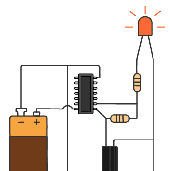
Imagine that you have a digital signal that transitions from 0V to 5V (0 and 1), for example from an Arduino, and you want to control a 24V lamp. Well you couldn’t use directly the digital signal, but you could use NPN transistors as follows:
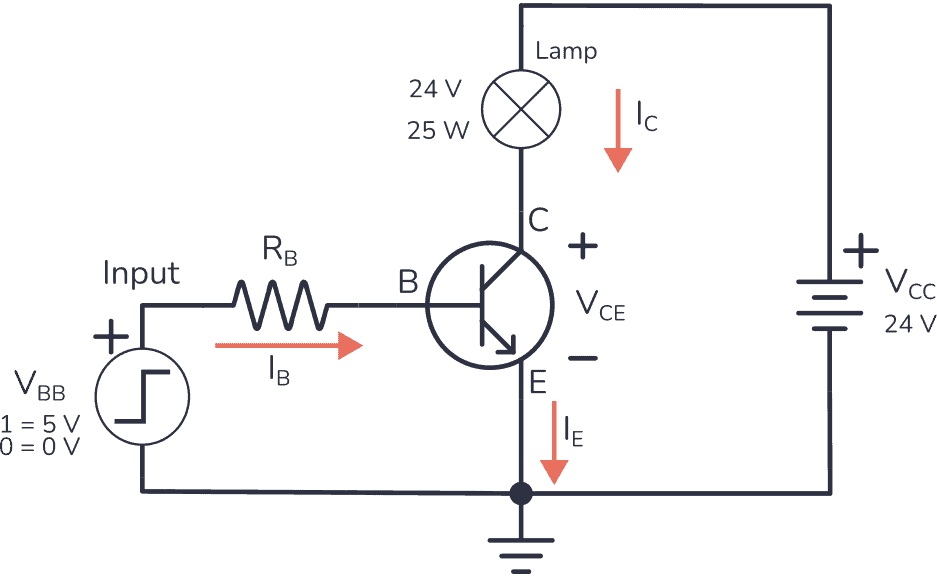
When the input signal is set to 5V, current flows through RB, causing the transistor to act as a closed switch, turning on the lamp.
When the digital input signal is 0, no voltage is applied, and consequently, no current flows through RB. This causes the transistor to act as an open switch, turning off the lamp.
Note: In this circuit, we are using a digital input signal, but you can replace it with any DC signal. For example, it could be a push button connected to a DC power supply
How to Choose the Base Resistor
Bipolar transistors are controlled by the base current you apply. The current going from collector to emitter can be found by multiplying the current going from base to emitter with the gain (β) of the transistor. Like this:

So, picking the right resistance value for RB is pretty important.
Since the base-to-emitter part of a BJT acts as a diode, calculating the base resistor works just like when using resistors with LEDs:
When you place a resistor in series with a diode, the diode grabs whatever voltage it needs (0.7V for base-to-emitter diode), and the rest drops across the resistor. So you can calculate the current through the base resistor like this:

To decide on the value for RB, you first need to know the current that your load needs. This is the collector current, Ic. If you have a lamp that needs 1 A, and a transistor with a gain of 100, then you’d need a base current, IB, of:

Now that you know how much IB you need, you can use Ohm’s law to find the resistor value.
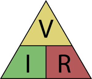
Place your hand across what you want to find, resistance (R), and you’re left with voltage (V) over current (I):


Note: A transistor will have current limitations. Many common-purpose transistors will only give you up to 100 mA. So for a current of 1A, it’s important to choose a transistor that can handle it.
The PNP Transistor as a Switch
A PNP transistor works the same way as an NPN transistor for switching operations, but the current flows in the opposite direction.
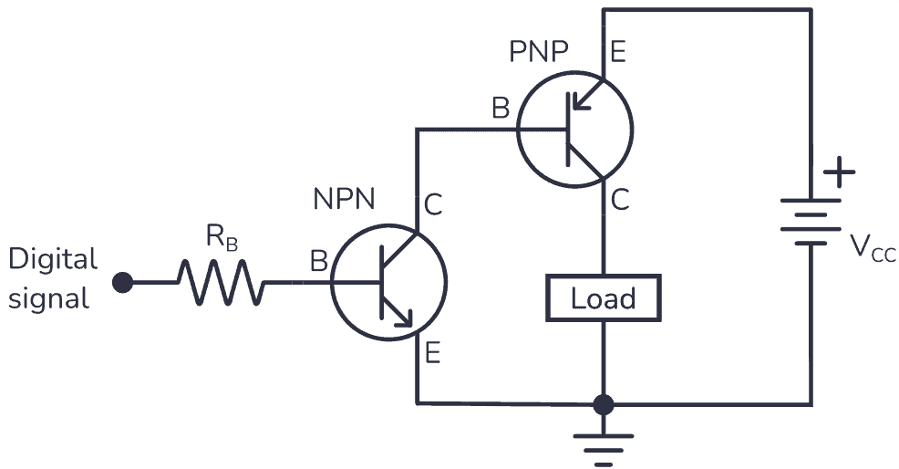
Let’s try to turn on / off the 25 W lamp again using the PNP transistor in its common emitter configuration:
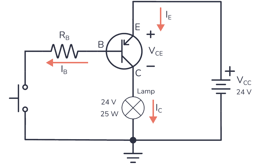
As you can see above, instead of providing a digital signal to drive the transistor, the circuit now includes a push button. We will learn how to use a digital signal later.
The PNP common-emitter setup may seem weird because the emitter is connected to the positive terminal of the power supply. But since the currents flow in the opposite direction it means the base has to be more negative than the emitter to turn the PNP on.
So the lamp is still connected to the collector, but now it is connected to the negative terminal of the power supply.
When the push button is open, no current flows through the base, which means the transistor is not activated and acts as an open switch, causing the load to be off. But when you press the push button, current flows through the base and the collector, making the transistor act as a closed switch and turning on the lamp.
How to Choose the Base Resistor
The calculations we did for the base resistor of the NPN transistor are more or less the same for the PNP transistor.
For example, if the lamp requires 1 A and you use a transistor with a β of 50, IB would be…

So, as before, once you have the IB current, you just need to apply Ohm’s law. There is a slight difference from what we did in the NPN transistor, as VRB is the voltage difference between VCC and VBE.

PNP Transistor With a Microcontroller
Whenever the voltage at the base of the PNP transistor is below VCC, the transistor would be activated, making it impractical to directly connect a digital signal to the base. To control a PNP transistor with any digital signal, you can use the Sziklai configuration:
MOSFET as a Switch
MOSFET transistors have three legs: Source (S), Gate (G), and Drain (D).

One of the main differences between MOSFETs and BJTs is that BJTs are controlled by the current through the base, while MOSFETs are controlled by the voltage at the gate.
Just as with BJTs, there are two types of MOSFETs, the nMOS and the pMOS. Let’s see how to use them as switches.
nMOS Transistor as a Switch
An nMOS transistor works like this: When a voltage higher than the transistor’s threshold voltage (VTH) is applied between the gate and the source, a current can flow from the drain to the source, making the transistor work as a closed switch.
If 0V is applied to the gate, no current will flow, so the transistor will behave like an open switch.
Let’s try to turn on the lamp:
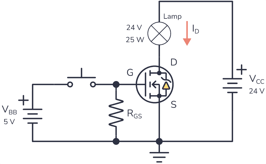
In the above circuit, the lamp is connected to the drain and the positive terminal of a DC power supply, and the source is connected to the negative terminal.
When the pushbutton is pressed, the positive voltage between the gate and the source enables current to flow from drain to source, turning on the lamp.
Make sure that the voltage you use for the gate is a bit higher than the voltage threshold (VTH) stated by the manufacturer. For example, the IRF510 MOSFET has a VTH of 2.0V, so you could use 5V without any problems.
In the opposite case, when the pushbutton is open, the lamp will be off because current cannot flow.
You may wonder, and what about RGS? Well, the gate needs a pull-down resistor to ensure transistor deactivation. This is because the gate-to-source part of a MOSFET behaves like a capacitor. So if you leave the gate floating after it has been connected to a voltage, this voltage stays at the gate and keeps the transistor on.
The value of RGS isn’t crucial; a 10 kΩ resistor should work fine.
pMOS Transistor as a Switch
The pMOS transistor works like this: To turn the transistor on, the voltage from source to gate must be higher than the threshold voltage (VTH) of the transistor. This is opposite from the nMOS where it was the voltage from gate to source that had to be higher than VTH.
What you really need to do is ensure that the gate is more negative than the source. For this, you can use the following circuit:
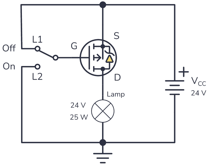
As you can see in the circuit diagram above, the lamp is now connected to the negative terminal of the DC power supply and to the drain, while the source is connected to the positive terminal.
The gate of the MOSFET is controlled by a switch. When it makes contact with L2, the gate becomes more negative than the source, turning on the lamp.
When the switch makes contact with L1, the voltage between the gate and the source is 0V, which turns off the lamp.
Do MOSFETs need a gate resistor?
The short answer is no, but it all depends on the application. For example, if you are going to drive an N-channel MOSFET with a microcontroller with output pins that are sensitive to overcurrent, you should use the following circuit:
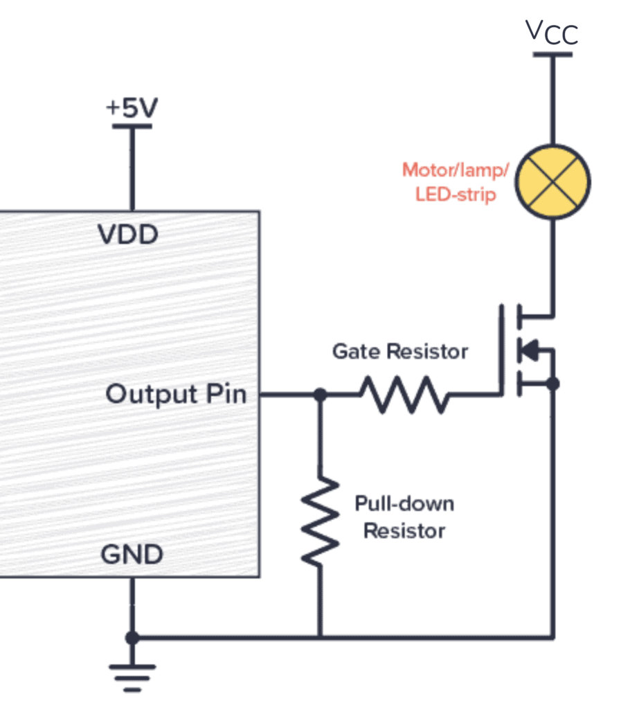
Using a MOSFET with a digital device without a gate resistor will most likely work, but adding one can help prevent potential overcurrent problems. You can learn more about this in our article about the MOSFET gate resistor.
More Transistors Tutorials

Oyvind's Circuit Tips
Get my tips for learning electronics, curious circuits, useful tutorials, hints for choosing components and much more via email.