The CD4008 is a CMOS chip that can add two 4-bit binary numbers. The result is given right away as a 5-bit number. It is called a 4-Bit Full Adder.
Pin Overview
| Pin Name | Pin # | Type | Description |
|---|---|---|---|
| VDD | 16 | Power | Supply Voltage (+3 to +15V) |
| GND | 8 | Power | Ground (0V) |
| A0 to A3 | 7, 5, 3, 1 | Input | Bits 0 to 3 for input number A |
| B0 to B3 | 6, 4, 2, 15 | Input | Bits 0 to 3 for input number B |
| CIN | 9 | Input | Carry-In bit |
| S0 to S3 | 10, 11, 12, 13 | Output | Bits 0 to 3 for output sum S |
| COUT | 14 | Output | Carry Out bit (Bit 4 of S) |
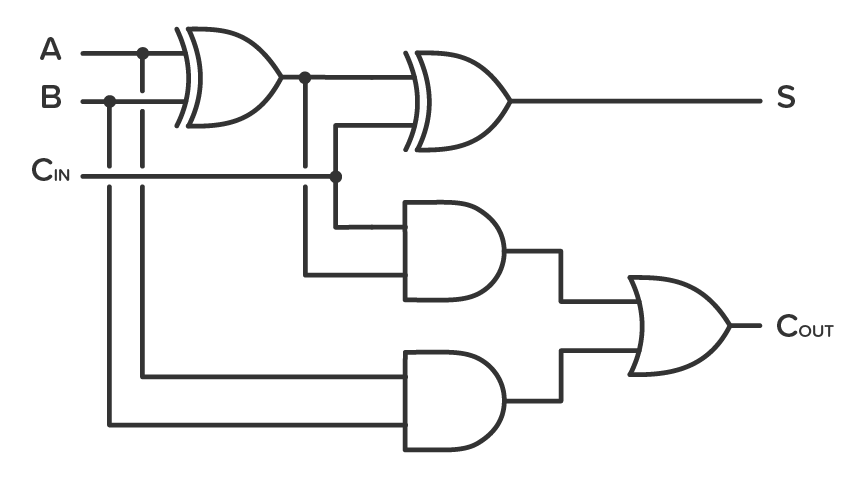
What is a Full Adder?
An adder is a circuit that adds two binary numbers. An adder is either a half adder or a full adder. The difference is that the full adder also has a Carry-In bit, while the half adder does not.
It’s made out of logic gates, like this:
| Carry-In | A | B | Sum (S) | Carry Out |
|---|---|---|---|---|
| 0 | 0 | 0 | 0 | 0 |
| 0 | 1 | 0 | 1 | 0 |
| 0 | 0 | 1 | 1 | 0 |
| 0 | 1 | 1 | 0 | 1 |
| 1 | 0 | 0 | 1 | 0 |
| 1 | 1 | 0 | 0 | 1 |
| 1 | 0 | 1 | 0 | 1 |
| 1 | 1 | 1 | 1 | 1 |
How To Use the CD4008
To be able to use the Full Adder in the chip, you must first connect the VDD pin and GND pin to the power supply. You can use a power supply voltage of anywhere from 3V to 15V.
Some versions of the chip support up to 20V. Check the datasheet of your version of the chip for exact values.
The A0 to A3 pins are the inputs for the 4 bits of number A.
The B0 to B3 pins are the inputs for the 4 bits of number B.
The CIN pin is the input for a Carry-In bit. It’s only used if you are combining several adders. Set to LOW when not in use.

10 Simple Steps to Learn Electronics
Electronics is easy when you know what to focus on and what to ignore. Learn what "the basics" really is and how to learn it fast.
The S0 to S3 pins are the outputs for the 4 bits of the sum S.
The COUT pin is the output for the 5th bit of the sum S (or the Carry Out bit).
Example Circuit: Adding Numbers With Switches
What better way to show how a binary adder works than to, well, add two binary numbers!
This is a practical circuit example that you can build using a CD4008 IC. You’ll use two 4-way DIP switches to set the two numbers you want to add. And you use LEDs to show the result. By using a different-colored LED for the Carry Out bit, it’s easier to remember which LED is the Carry Out.
The resistors R1 to R8 are pulldown resistors to pull the pins LOW when they are not connected HIGH.
The resistors R9 to R13 control the current to the LEDs. They are not there just to protect the LEDs, but also to make sure you don’t pull too much current out of the chip. If you need more than 1 mA per output, consider adding a transistor.

To build this you’ll need:
- A 4-bit Full Adder chip such as the MC14008B
- Two 4-way DIP switches (S1 and S2)
- Eight 10 kΩ pulldown resistors (R1-R8)
- Five 1k-10kΩ resistors for limiting current to LEDs (R9-R13)
- Four red LEDs (L1-L4)
- A green LED (L5)
Alternatives and Equivalents for CD4008
You likely find the 4008 IC marked as MC14008, HCF4008, TC4008, or HEF4008. Usually with a few extra characters at the end (Ex: MC14008B).
This has to do with the manufacturer of the chip and the technology used. But the functionality and the pins are the same.
If you can’t find any of these in your local electronics store, check out my list of online stores where you can find components and tools for all your electronics projects.
Or try one of the following IC alternatives with Full Adder functionality:
- 74HC82: 2-bit Full Adder
- 74HC83: 4-bit Full Adder
4008 Datasheet
Download the PDF datasheet for the IC 4008 here:
CD4008BMS (Intersil)
MC14008B (On Semiconductor)
Build Something Useful This Evening
This gadget lets you use any IR remote-control to control your lamp, garden lights, heater oven, garage door, or anything else.