The 74×03 (ex 74HC03) is a chip that’s got four open-collector NAND gates. This type of output makes it simple to connect it to other chips that use different logic levels. However, it also means you can’t just swap it out with a regular NAND gate chip.
In this guide, you’ll learn everything you need to know about the 74HC03 and how you can use its NAND gates in your own circuit.
What does the 74HC03 / 74LS03 do?
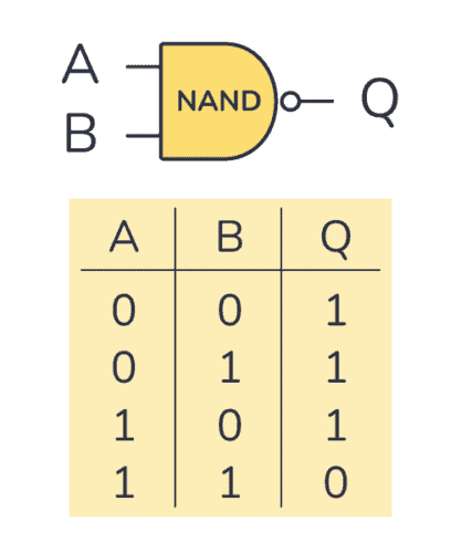
The 74×03 gives you four open-collector NAND gates that can be used individually. A NAND gate is a logic gate that outputs 0 (LOW) only if all of its inputs are 1 (HIGH). In the truth table below, you can see what the output will be for any given input:
How To Use This Chip
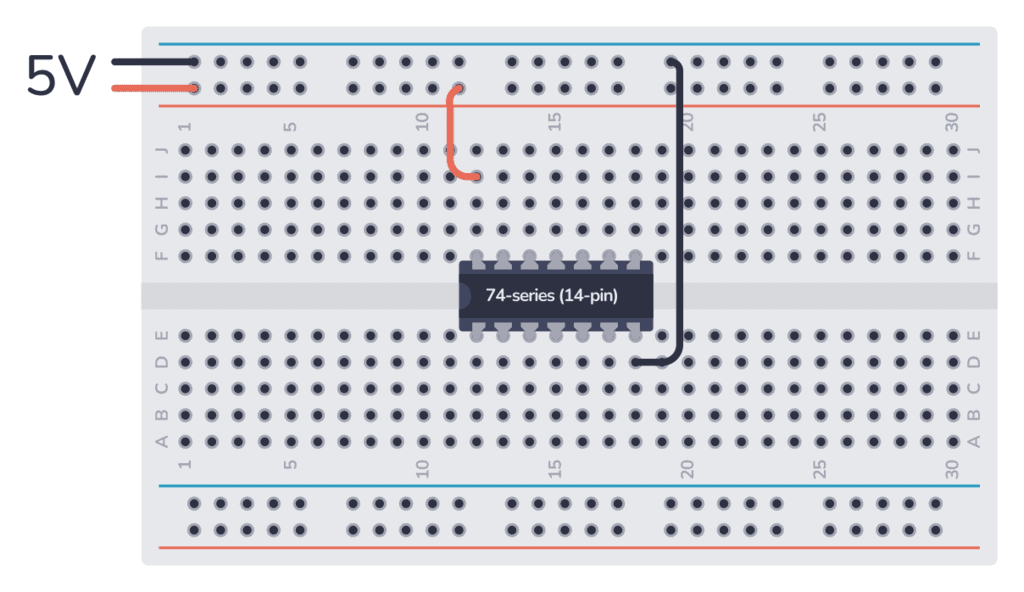
The 74HC03 comes in a 14-pin package and needs to be hooked up to power before you can use it. Most 7400 ICs like this one support 5 volts. But there’s a difference between the HC and LS version – the 74HC03 can handle 2 to 6 volts, while the 74LS03 can only do 5 volts.
Once you’ve connected the VCC and GND pins to power, you can use any of the four open-collector NAND gates inside.
This chip uses open-collector outputs which means you can only sink current, not source it.
The output of each gate in the 74HC03 can sink around 4 milliamps when it’s powered with 5 volts. On the other hand, the 74LS03 can usually handle about 8 milliamps of current. But, these values might differ depending on the chip manufacturer.
How To Use Open-Collector Outputs
The outputs from the 74HC03 are not your normal high/low outputs. Instead, they use something called open-collector. Open-collector outputs are outputs that are connected via a transistor. And the collector of the transistor is available at the pin. For a NAND gate, it will look like this:
Get the 555 Timer Cheatsheet
A super helpful reference that makes it easy to design circuits, so that you can build oscillators, timer circuits, and more in no time.
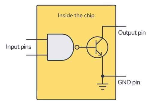
So when the output from the NAND gate is ‘1’, it turns on the transistor that is connected to the output. When the output from the NAND gate is ‘0’, it means the transistor will be off.
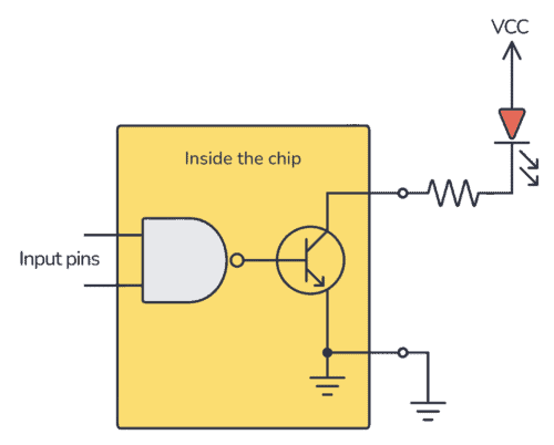
To turn on an LED when the NAND gate output is ‘1’, you must connect the LED from your positive supply, via a resistor, to the open-collector output:
If you instead want to get your standard high/low output, you can get this by connecting a resistor from the output up to your positive supply. Then your NAND gate output pin becomes a standard high/low output.
The advantage of using open-collector outputs is that you can choose your HIGH voltage level to make it compatible with whatever the voltage is of the next stage. The resistor acts as a pull-up resistor and makes the HIGH level approximately the same as the VCC voltage that you provide.
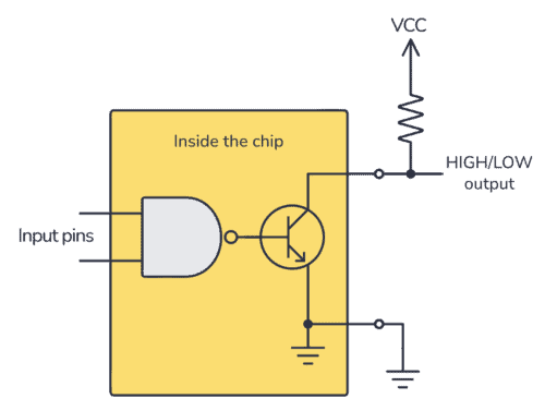
It’s important to notice that the output will be inverted: A logical HIGH from the NAND gate turns the transistor ON so that the output voltage on the pin becomes low. A logical LOW leaves the transistor OFF so that the output voltage on the pin becomes HIGH.
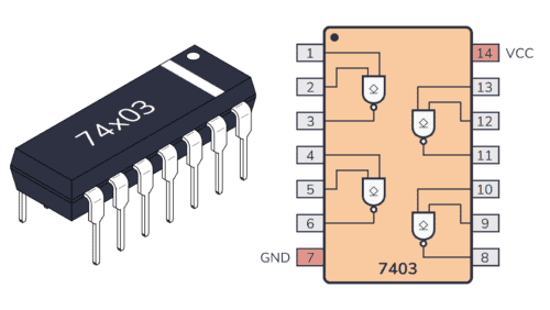
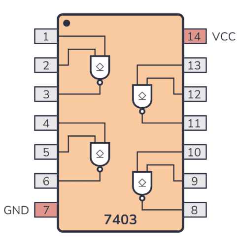
74×03 Pinout
The 74×03 has 14 pins and contains four open-collector NAND gates laid out as shown in the pinout diagram below. Each gate has the open-collector symbol, reminding you of the type of output:
| Pin # | Type | Description |
|---|---|---|
| 1 | Input | Input to the first NAND gate. |
| 2 | Input | Input to the first NAND gate. |
| 3 | Output | Open-collector output from the first NAND gate. |
| 4 | Input | Input to the second NAND gate. |
| 5 | Input | Input to the second NAND gate. |
| 6 | Output | Open-collector output from the second NAND gate. |
| 7 | Power | Connect to ground (GND). |
| 8 | Output | Open-collector output from the third NAND gate. |
| 9 | Input | Input to the third NAND gate. |
| 10 | Input | Input to the third NAND gate. |
| 11 | Output | Open-collector output from the fourth NAND gate. |
| 12 | Input | Input to the fourth NAND gate. |
| 13 | Input | Input to the fourth NAND gate. |
| 14 | Power | Positive power supply (VCC). Connect to +5V power. |
74HC03 Circuit Example: Level Shifter
Here’s a simple example circuit that illustrates how to build a 5V to 3.3V level shifter from a logic NAND gate in the 74HC03 IC. This way you can, for example, connect an Arduino with 5V outputs to an ESP32 microcontroller that only supports 3.3V inputs:
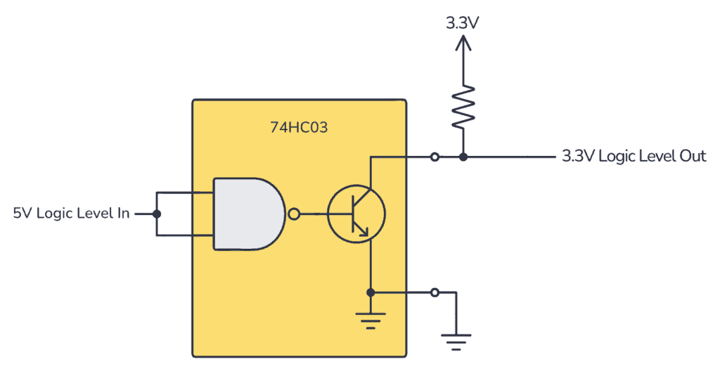
To build this circuit, you’ll need the following parts:
- IC: 74HC03
- Resistor: 10 kΩ
Alternatives and Equivalents for 74HC03 / 74LS03
There are many versions of the 74×03 chip. They all have the same functionality, but with different specifications such as supported voltages and maximum current output.
Here’s a list of a few equivalents of this chip:
- 74HC03 (High-speed CMOS)
- 74HCT03 (High-speed CMOS, TTL compatible)
- 74LS03 (High-speed TTL)
- 74LVC03 (Low Voltage TTL)
- 74AC03 (Advanced CMOS)
- 74ALS03 (Advanced Low-Power Schottky TTL)
- 74F03 (Very High Speed)
- 74C03 (CMOS, similar to the 4000-series)
Some manufacturers also add a prefix, such as the SN74HC03 and SN74LS03 by Texas Instruments.
Can’t find the 74×03 anywhere? Then try one of the following IC alternatives:
- 74×00 – Quad 2-input NAND gates.
- 74×132 – Quad 2-input NAND gates (with Schmitt-trigger inputs).
- CD4011 – Quad 2-input NAND gates.
- CD4093 – Quad 2-input NAND gates (with Schmitt-trigger inputs).
If you can’t find the 74×03 IC in your local electronics store, don’t worry, you’ll most likely find it in one of the stores listed on this page of online stores where you’ll find components and tools for all your electronics projects.
Datasheet for the 74LS03 and 74HC03 chips
Download the PDF datasheet for your version of the 74×03 here:
10 Simple Steps to Learn Electronics
Electronics is easy when you know what to focus on and what to ignore. Learn what "the basics" really is and how to learn it fast.