The 74HC7002 is a cool little chip that has four Schmitt-trigger NOR gates. Schmitt-trigger gates are great because they are more robust against noise. But my favorite thing about them is that they make it easy to build oscillators for all sorts of fun circuits. And yes, they also work as replacements for normal NOR gates.
In this guide, you will learn everything you need to know about this chip and how you can use its NOR gates in your own projects.
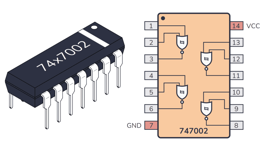
What does the 74HC7002 do?
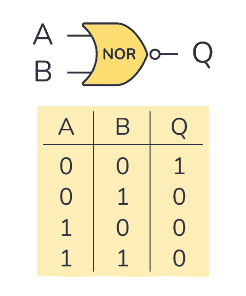
The 74HC7002 gives you four Schmitt-trigger NOR gates that can be used individually. A NOR gate is a logic gate that outputs 1 (HIGH) if all of its inputs are 0 (LOW). In the truth table below, you can see what the output will be for any given input:
What is a Schmitt Trigger?
The fact that the gate inputs are Schmitt-triggered means that the threshold for going from 0 to 1 on the input is different from the threshold for going from 1 to 0.
For example, if you power this chip with three AA batteries (4.5V), you need the voltage on the input to go above 2V before it’s accepted as a 1 (HIGH). Once it’s HIGH, the voltage needs to drop below 0.9V for the input to be accepted as a 0 (LOW). (You can find these values from the datasheet).
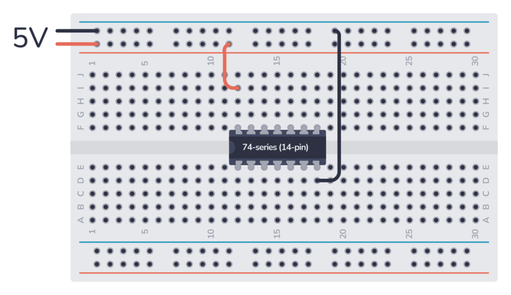
How To Use This Chip
The 74HC7002 comes in a 14-pin package, and you need to connect it to power before you can use it. It supports a supply voltage of 2V to 6V. And each output can sink or source around 4 mA when powered with 5V.
Once it’s connected, you can use any of the four Schmitt-trigger NOR gates inside.
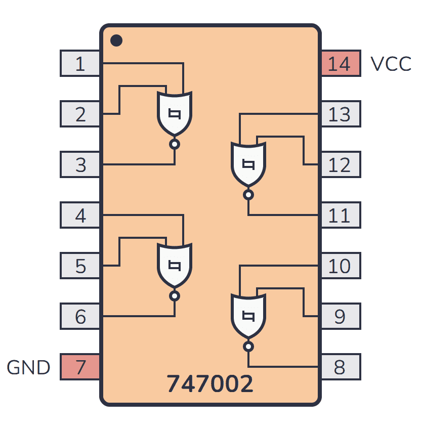
74HC7002 Pinout
| Pin # | Type | Description |
|---|---|---|
| 1 | Input | Input to the first NOR gate. |
| 2 | Input | Input to the first NOR gate. |
| 3 | Output | Output from the first NOR gate. |
| 4 | Input | Input to the second NOR gate. |
| 5 | Input | Input to the second NOR gate. |
| 6 | Output | Output from the second NOR gate. |
| 7 | Power | Connect to ground (GND). |
| 8 | Output | Output from the third NOR gate. |
| 9 | Input | Input to the third NOR gate. |
| 10 | Input | Input to the third NOR gate. |
| 11 | Output | Output from the fourth NOR gate. |
| 12 | Input | Input to the fourth NOR gate. |
| 13 | Input | Input to the fourth NOR gate. |
| 14 | Power | Positive power supply (VCC). Connect to +5V power. |
74HC7002 Circuit Example
Here’s a simple project you can build with the NOR gates in the 74HC7002 IC.
10 Simple Steps to Learn Electronics
Electronics is easy when you know what to focus on and what to ignore. Learn what "the basics" really is and how to learn it fast.
The NOR gates make up an SR latch that remembers the last output value it had. It controls an LED that you can turn on by pressing the On button. It will stay on even after you release the button. To turn the LED off, press the Off button.

To build this circuit, you’ll need the following parts:
- 1 x 74HC7002
- 1 x LED (L1)
- 2 x 10 kΩ resistor (R1-R2)
- 1 x 1 kΩ resistor (R3)
- 2 x pushbutton (S1-S2)
Alternatives for 74HC7002
Can’t find the 74HC7002 anywhere? Then try one of the following IC alternatives:
- 74HC02 – Quad 2-input NOR gates.
- 74HC33 – Quad 2-input NOR gates (with open-collector outputs).
- CD4001 – Quad 2-input Schmitt-trigger NOR gates.
If you can’t find this IC in your local electronics store, don’t worry, you’ll most likely find it in one of the stores listed on this page of online stores where you’ll find components and tools for all your electronics projects.
Datasheet for the 74HC7002 chip
Download the PDF datasheet for your version of the 74×7002 here:
10 Simple Steps to Learn Electronics
Electronics is easy when you know what to focus on and what to ignore. Learn what "the basics" really is and how to learn it fast.