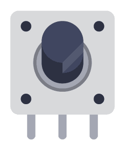
Rotary encoders are components used for measuring the rotation of a shaft or axle. They are often used for volume knobs in audio equipment, DIY gaming controllers, or as an input device for different Arduino or Raspberry Pi projects.
In this guide, you’ll learn how rotary encoders work and how they can be integrated into various projects. The intended audience is hobbyists and DIY enthusiasts who plan on using rotary encoders in their circuits.
Types of Rotary Encoders
There are two types of rotary encoders:
- Absolute encoder
- Incremental encoder
The absolute rotary encoder will give you the absolute rotational position of the shaft. The incremental rotary encoder will give you “steps” in either direction so that you can know which direction it has been turned and how fast.
The incremental rotary encoder is the most common one and is the one we’ll focus on in this article.
How Rotary Encoders Work
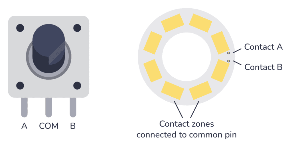
Inside the rotary encoder, there’s a disc of evenly spaced contact zones that rotate when you rotate the shaft. These contact zones are connected to the common pin. Below this disc, there are two stationary contacts, each connected to one of the other two pins.
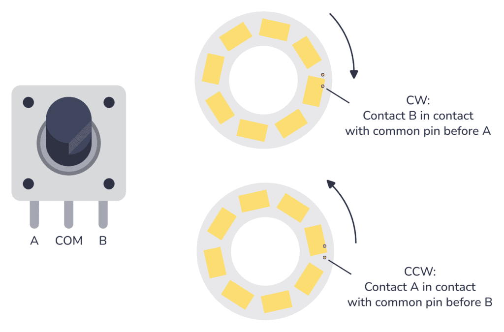
When you rotate the shaft one way, the contact zone inside will make contact with contact B first, before making contact with contact A. When you rotate the other way, the contact zone inside will make contact with contact A first.
By checking which of the two contacts connected with the pad first, you can determine the direction of rotation.
10 Simple Steps to Learn Electronics
Electronics is easy when you know what to focus on and what to ignore. Learn what "the basics" really is and how to learn it fast.
Connecting a Rotary Encoder
The rotary encoder has three pins; A, B, and COM.
The A and B contacts work as switches that will be connected down to the COM pin when closed. You can connect the COM pin to GND to get a LOW signal every time any of them come in contact with the common pin. Then use a pull-up resistor for each pin (A and B) so that they are normally HIGH.
To avoid contact bouncing, a filter circuit is normally used. This is just a resistor and a capacitor. You can usually find a filter circuit example from the datasheet of your rotary encoder.
Below is the suggested circuit from the PEL12S encoder datasheet:
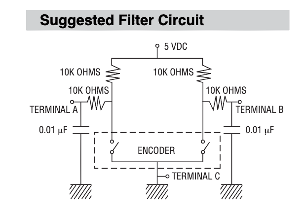
It’s not super obvious how to go from that example circuit to a real-world circuit where you connect an incremental rotary encoder to for example an Arduino or a Raspberry Pi. But if you look closely you’ll see that you’ll end up with a schematic that looks like this:
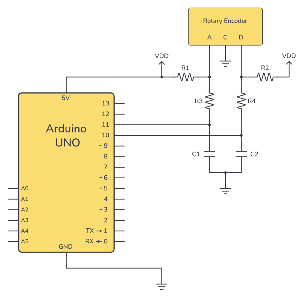
Then you just need to add code that checks if Pin A goes LOW before Pin B goes LOW (direction A), or if it’s the other way around (opposite direction).
Check out our Arduino rotary encoder guide to see the complete code example and breadboard layout for the above circuit that you can build and test out in practice.
More Electronic Components Tutorials
Free Course: Blinking a Light
Join my free email course on how to build a circuit that blinks a light. Enter your details below and you'll receive the first lesson right away: