Electrical relays are switches that you turn on and off with electrical signals. In this guide, you’ll learn how a relay works and how to use relays in your own electronics projects!
Relays are very important in electronics because you can use them to turn on/off high-power devices like lamps or garage door motors with just a small DC voltage signal.
You can use a microcontroller, such as Arduino, to create the logic for when to turn your lamp on and off, then use an electrical relay to do the switching of the lamp.
This makes it easy to make lights that activate only at night, control your garage door motor with a signal generated by your phone, or control other home appliances.
How a Relay Works
A relay consists of an electromagnet and a mechanical switch.
An electromagnet is a simple device made up of a wire wound in a coil around a core of ferromagnetic material such as iron.
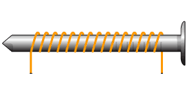
This is a very interesting device and it is easy to build one yourself. All you need is an iron nail and some insulated wire. Wind the wire into a coil around the nail and apply power. Your nail becomes magnetic!
Note that it can get very hot if you have too few windings or too much voltage!
Free Course: Blinking a Light
Join my free email course on how to build a circuit that blinks a light. Enter your details below and you'll receive the first lesson right away:
Inside the Relay
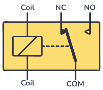
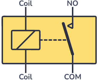
Below you can see the relay pins and the symbol of a typical 5-pin relay.
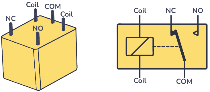
The coil pins control the switch, and the NC, NO, and COM pins make up the switch.
Inside a relay, there is an electromagnet, a switch, and some mechanical parts to change the state of the switch when the electromagnet is turned on.
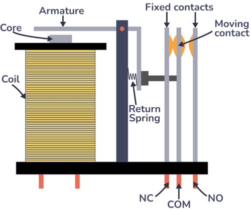
Here are the main parts inside the relay:
- Coil and core: A coil wound around a magnetic core makes up an electromagnet. It generates a magnetic field around it when an electrical current passes through the coil.
- Armature: The armature is a movable component within the relay. When the coil is energized, the magnetic field it produces attracts the armature, causing it to move.
- Return Spring: The return spring is connected to the armature, providing a restoring force when the coil is de-energized. It ensures that the armature returns to its original position when the electrical current through the coil ceases.
- Moving Contact: Attached to the armature through the return spring, the moving contact physically moves with the armature. When the armature is attracted by the energized coil, the moving contact changes its position, either making or breaking contact with the fixed contacts.
- Fixed Contact – Normally Closed (NC): The NC contact is closed (connected to COM) when the relay is not energized.
- Fixed Contact – Normally Open (NO): The NO contact is open (disconnected from COM) when the relay is not energized.
Relay Wiring Diagram Using a Transistor
Below is a relay wiring diagram that shows how to use a relay switch with an NPN transistor. This is useful for when you want to control a relay from things that can’t drive relays, like an Arduino, or an integrated circuit from the 4000 series or 7400 series.
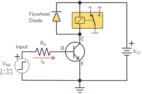
The NPN transistor’s base receives current through the base resistor RB, activating the transistor. This allows current to flow from collector to emitter, energizing the coil inside the relay.
When the transistor switches off, the magnetic field produced by the coil collapses, inducing a voltage spike. The flywheel diode provides a path for this spike, protecting the transistor from damage.
If you want to learn more about how the transistor works and how to calculate the base resistor RB, you can check out our guide for using the transistor as a switch.
Automatic Street Light circuit with an LDR and Relay
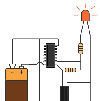
You might have noticed street lights that automatically turn on at night and off during the day. Knowing how relays work, you can create a circuit capable of controlling these types of lights using just a photoresistor, two NPN transistors, and a relay:
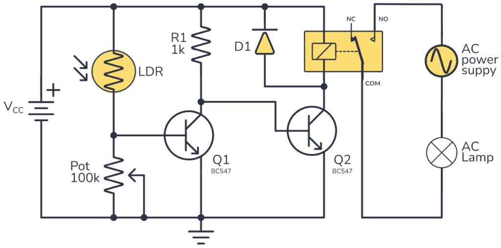
The circuit uses an LDR (Light Dependent Resistor) as a light sensor, which, in simple terms, is a resistor whose value increases in darkness and decreases in the presence of light. Then it uses one transistor to detect the light, and another to drive the relay.
When light falls on the LDR, its resistance decreases, activating transistor Q1. That means the collector output of this transistor goes LOW since there is almost no voltage across a transistor when it’s on. That means the second transistor is off because there is no current flowing through its base, meaning the relay coil does not get any current, so the street light is off.
During night-time, the resistance of the LDR increases to a high value, practically halting the current flow through transistor Q1, deactivating it. With Q1 now acting as an open switch, the current flows directly through R1 to transistor Q2, activating it and allowing current to flow through the collector, energizing the relay coil and turning on the street light.
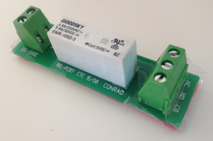
For circuits like these, and can be useful to use a relay module that comes with proper screw terminal contacts with proper current rating:
Types of Relays
There are two main types of relays: solid-state relay (SSR) and electromechanical relay (EMR).
In practice, you use them the same way. The main difference is that the SSR has control pins instead of coil pins.
But on the inside, they are very different:
An electromechanical relay uses mechanical components that move. A solid-state relay uses semiconductors and there are no moving parts. This means that a solid-state relay can switch much faster and does not wear out like a relay does.
Within electromechanical relays, you can also find these relay types:
- Latching Relay: Latching relays have two stable states and will remain in the last state it was in when last powered. They only consume power when switching between states, making them energy-efficient for applications like memory backup or power cycling.
- Reed Relay: Reed relays use a reed switch enclosed in a coil to control the switching action. They are compact and suitable for high-speed switching applications.
- Polarized Relay: Polarized relays have contacts that are polarized to ensure proper operation in DC circuits. They are designed to prevent reverse polarity issues.
- High-Frequency Relay: These relays are designed to operate reliably at high frequencies, making them suitable for applications where the cycle of on/off occurs in short periods.
Relay Switch Types
SPDT Relay
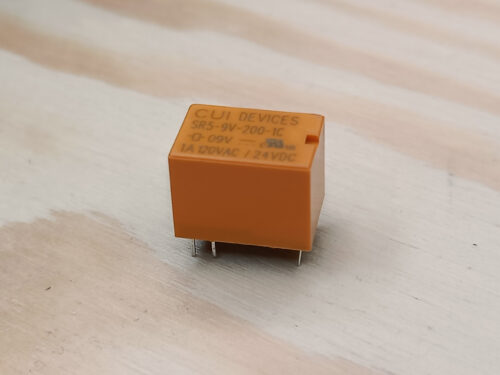
The relay I’ve used in my examples is called Single Pole Double Throw (SPDT). It’s the most commonly used. It’s a 5-pin relay with the following pins:
The COM pin is always used. And although you can use both NC and NO, it’s common to use just one of them.
Normally Open (NO) Pin Connection
If you want the device that you want to switch on/off to be disconnected from power when the relay is not activated, you need to use the normally open (NO) pin.
As soon as the relay coil receives power, the switch closes, completing the circuit and allowing electricity to flow through it so that whatever you’ve connected turns on.
Normally Closed (NC) Pin Connection
If you want the device that you want to control to be connected to power when the relay is not activated, you need to use the normally closed (NC) pin.
As soon as the relay coil receives power, it causes the switch to open, interrupting the circuit and stopping the flow of electricity to your device.
Single Pole Single Throw (SPST)
This relay has one normally open (NO) and one common (COM) contact. It can either connect or disconnect a single circuit.
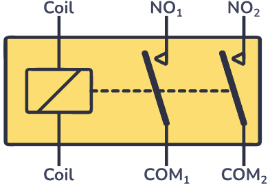
Double Pole Single Throw (DPST)
DPST relays feature two sets of contacts, each set capable of controlling a single circuit. Both switches can be open or closed simultaneously.
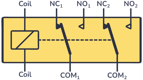
Double Pole Double Throw (DPDT)
DPDT relays have two sets of contacts, each set capable of controlling two separate circuits. It provides a double-throw functionality for each of the two poles.
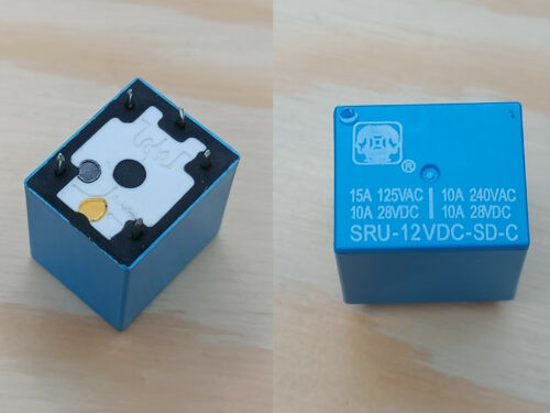
Notes of Caution
Always check the voltage and current rating of the relay switch. Some are designed for switching only low voltages, while others are meant for switching higher voltages.
I hope this simple guide has helped you to understand how a relay works. Now run along and start soldering some relay circuits!
Do you have any questions about how relays work or any feedback you want to share? Let me know in the comments below!
More Electronic Components Tutorials
Free Course: Blinking a Light
Join my free email course on how to build a circuit that blinks a light. Enter your details below and you'll receive the first lesson right away: