In this tutorial, you’ll learn how to interface an incremental rotary encoder with an Arduino to read the movement of the knob. This can be useful for creating user interfaces or reading mechanical positions in robotics and other applications.
What You Will Need
- Arduino board
- 1x Incremental Rotary Encoder (like this)
- 4x 10 kΩ Resistors (R1, R2)
- 2x 0.1uF Capacitors (C1, C2)
- Breadboard
Schematic and Breadboard Setup
Note that in this schematic I’m using a rotary encoder directly, so it needs a few extra components. But you can also buy rotary encoder boards that include these extra components on the board to make the connection simpler.
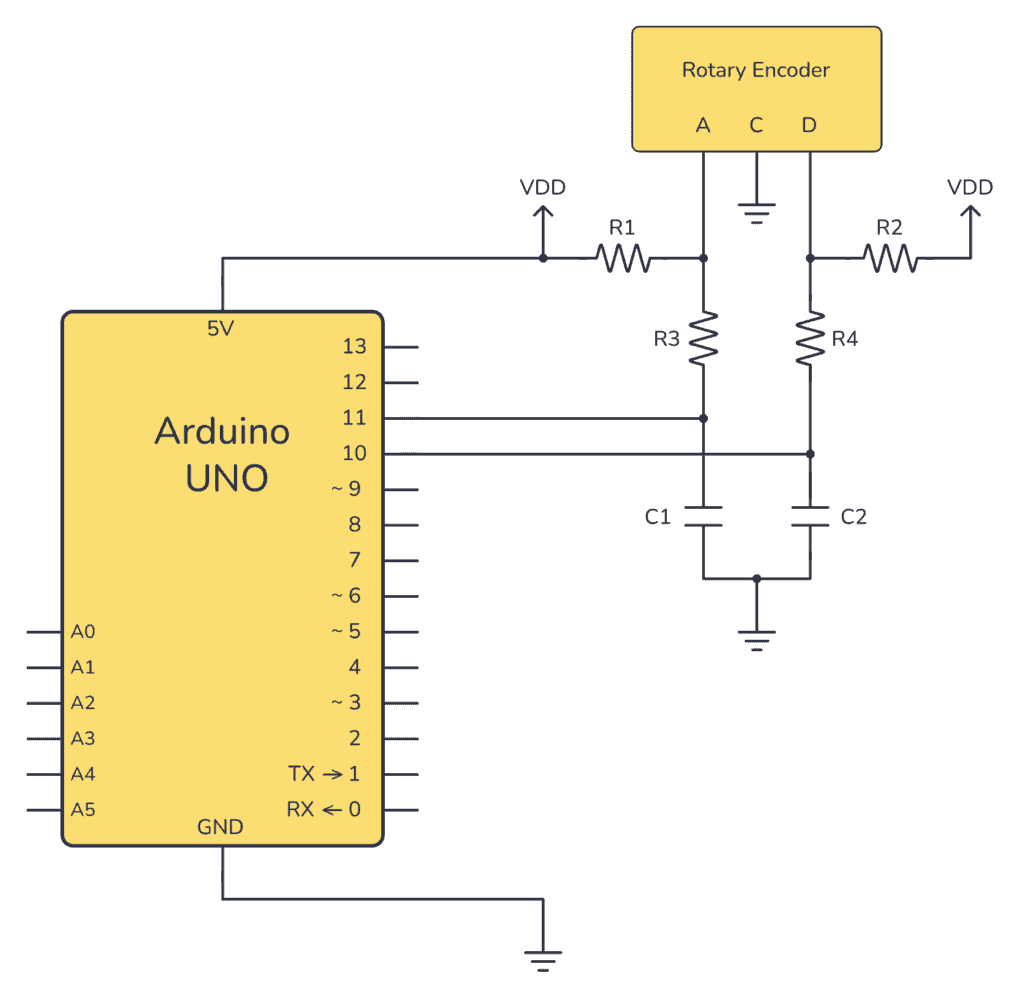
VDD in the schematics just refers to 5V from Arduino.
The connection of the extra components needed to hook up this rotary encoder was taken from the Suggested Filter Circuit from the rotary encoder’s datasheet. If you are using a different encoder, be sure to check the datasheet for the ‘Suggested Filter Circuit’ as it may be different.
How It Works
The circuit works by looking at the two pins A and B from the rotary encoder and checking which of them goes high before the other. If A goes high before B, that’s one direction. If B goes high before A, that’s the opposite direction.
Learn more from our guide on how rotary encoders work.
Connecting The Arduino Rotary Encoder Circuit
In the following image, you can see how to connect the complete example circuit onto a breadboard, and the wiring needed to connect it to the Arduino.
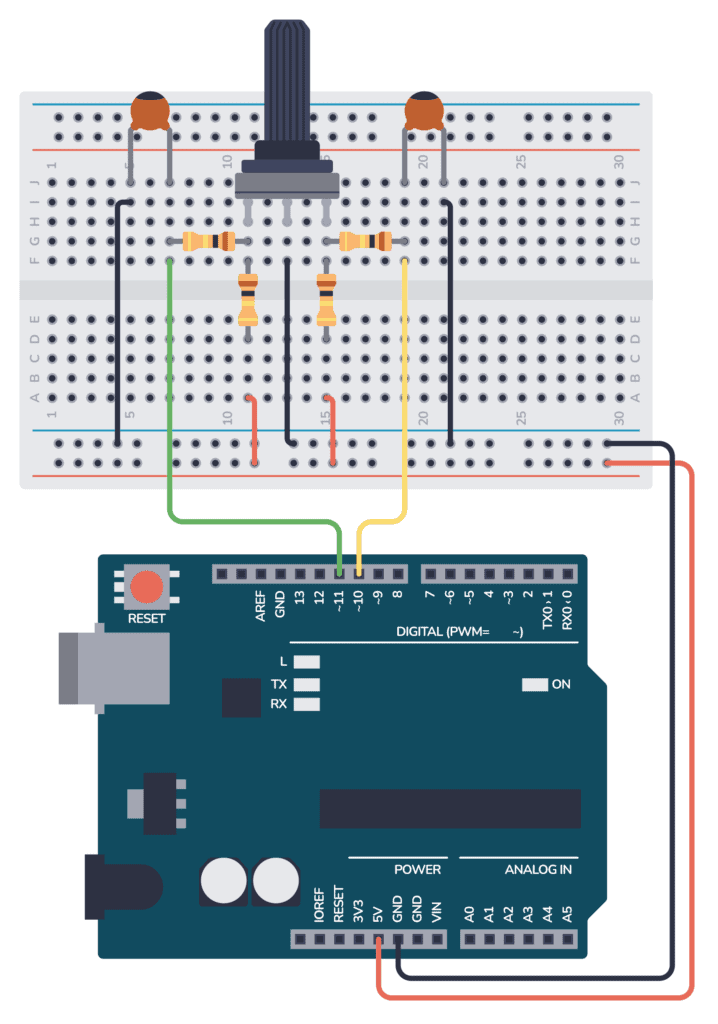
Step-by-Step Instructions
- Connect the rotary encoder to the breadboard.
- Place the two 10 kΩ resistors R1 and R2 from A and B to 5V.
- Place the two 10 kΩ resistors R3 and R4 from A and B to the Arduino digital pins 10 and 11, respectively.
- Place the 0.1uF capacitors (C1 and C2) as shown in the schematic to debounce the encoder signal.
- Connect point C to ground.
- Connect the Arduino to your computer with a USB cable.
The Code
Upload the following code to your Arduino. This code initializes the rotary encoder and uses interrupts to update the position count every time the encoder is turned.
Get Our Basic Electronic Components Guide
Learn how the basic electronic components work so that circuit diagrams will start making sense to you.
The result is printed to the Serial port so that you can read it out from the Serial Monitor.
// Define the pins used for the encoder
const int encoderPinA = 10;
const int encoderPinB = 11;

// Variables to keep the current and last state
volatile int encoderPosCount = 0;
int lastEncoded = 0;

void setup() {
  Serial.begin(9600);

  // Set encoder pins as input with pull-up resistors
  pinMode(encoderPinA, INPUT_PULLUP);
  pinMode(encoderPinB, INPUT_PULLUP);

  // Attach interrupts to the encoder pins
  attachInterrupt(digitalPinToInterrupt(encoderPinA), updateEncoder, CHANGE);
  attachInterrupt(digitalPinToInterrupt(encoderPinB), updateEncoder, CHANGE);
}

void loop() {
  static int lastReportedPos = -1; // Store the last reported position
  if (encoderPosCount != lastReportedPos) {
    Serial.print("Encoder Position: ");
    Serial.println(encoderPosCount);
    lastReportedPos = encoderPosCount;
  }
}

void updateEncoder() {
  int MSB = digitalRead(encoderPinA); // MSB = most significant bit
  int LSB = digitalRead(encoderPinB); // LSB = least significant bit

  int encoded = (MSB << 1) | LSB; // Converting the 2 pin value to single number
  int sum  = (lastEncoded << 2) | encoded; // Adding it to the previous encoded value

  if(sum == 0b1101 || sum == 0b0100 || sum == 0b0010 || sum == 0b1011) encoderPosCount++;
  if(sum == 0b1110 || sum == 0b0111 || sum == 0b0001 || sum == 0b1000) encoderPosCount--;

  lastEncoded = encoded; // Store this value for next time
}
Once you upload this code, you can open the Serial Monitor at a baud rate of 9600 to see the movement of the encoder change as you rotate it.
Troubleshooting
If the encoder values are erratic or do not change as expected, double-check your wiring against the schematic and ensure that your resistors and capacitors are correctly placed for debouncing.
More Arduino Tutorials
10 Simple Steps to Learn Electronics
Electronics is easy when you know what to focus on and what to ignore. Learn what "the basics" really is and how to learn it fast.