In this guide, you’ll learn how to set up an Arduino Hall effect sensor, specifically the US1881, to detect magnetic fields. This can be useful for projects where you need to find the RPM of a motor or other movements in a machine.
Parts Needed
- Arduino UNO
- US1881 Hall Effect sensor
- 10kΩ Resistor
- 4.7nF Capacitor
- Breadboard and Jumper Wires
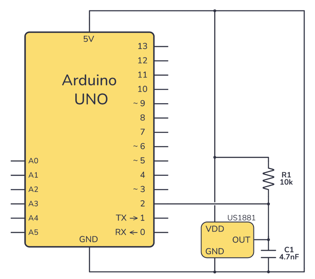
Schematic Diagram
Connect the VDD pin of the US1881 Hall effect sensor to 5V on the Arduino and the GND pin to GND.
This sensor uses an open-drain output, which means that you need a pull-up resistor to 5V in order to read out any value from it. The value of the resistor isn’t crucial. 1k to 100k will work fine.
The capacitor across the output stabilizes the output but could be skipped.
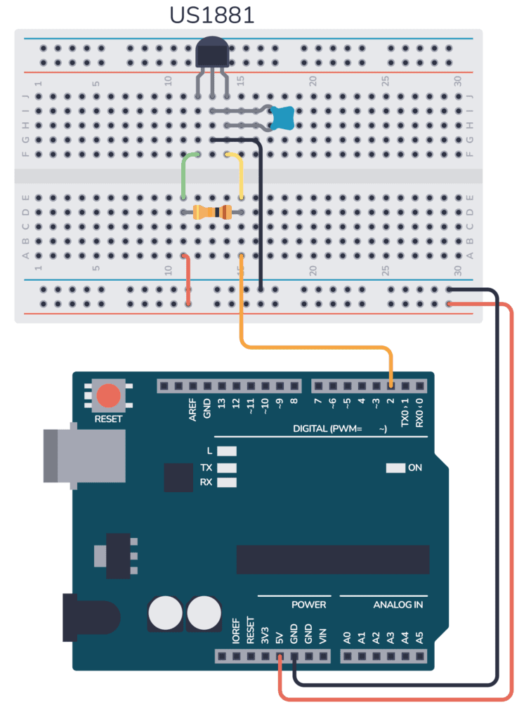
Here’s an example of how you can connect this circuit to a breadboard:
Arduino Hall Effect Sensor Test Code
To test the Hall effect sensor, you need to read the output pin, which is connected to Arduino digital pin 2. So basically all you need code-wise to read out the value is hallSensorState = digitalRead(D2);
Here’s the complete code to test your sensor:
const int hallSensorPin = 2;  // Hall Effect sensor connected to digital pin 2
int hallSensorState;          // Variable to store the state of the sensor

void setup() {
  Serial.begin(9600);                // Start serial communication at 9600 baud
  pinMode(hallSensorPin, INPUT);     // Set the Hall Effect sensor pin as an INPUT
}

void loop() {
  hallSensorState = digitalRead(hallSensorPin); // Read the state of the sensor

  // Check if the sensor is detecting a magnetic field
  if (hallSensorState == HIGH) {
    Serial.println("Magnetic field detected!"); // If yes, print this message
  } else {
    Serial.println("No magnetic field detected."); // If no, print this message
  }

  delay(1000); // Wait for 1 second before the next read
}
Step-by-Step Instructions
- Assemble the circuit as shown in the breadboard layout and schematic diagram above.
- Connect the Arduino to your computer with a USB cable.
- Open the Arduino IDE and copy the example code into a new sketch.
- Upload the sketch to your Arduino board.
- Open the Serial Monitor to view the output messages. You should see “Magnetic field detected!” when a magnet is near the sensor, and “No magnetic field detected.” when it’s not.
If you want to learn more details about this sensor, check out its datasheet.

10 Simple Steps to Learn Electronics
Electronics is easy when you know what to focus on and what to ignore. Learn what "the basics" really is and how to learn it fast.
Troubleshooting Tips
- Ensure all connections are secure and match the schematic.
- If the sensor always reads “HIGH,” check for any magnetic sources nearby, including the magnet inside the breadboard power rails.
- If the sensor does not detect a magnetic field, ensure the magnet is close enough to the sensor.
Conclusion
Now you know how to detect magnetic fields using a Hall Effect sensor with your Arduino. This setup can be used as a magnetic door sensor, for RPM counting, or in any project requiring magnetic field detection.
More Arduino Tutorials
Free Course: Blinking a Light
Join my free email course on how to build a circuit that blinks a light. Enter your details below and you'll receive the first lesson right away: