In this project, you will build a touch sensor circuit. It’s a cool and simple circuit that allows you to control an LED with the touch of a finger. And you only need three components, how cool right?
You can build this circuit if you’re a total beginner.
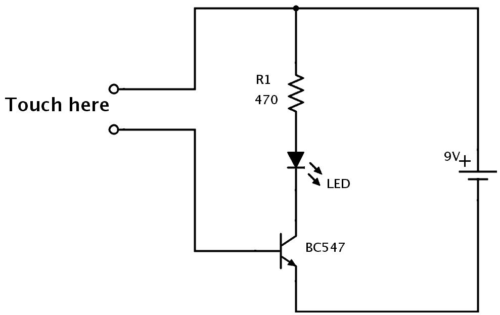
The Touch Sensor Circuit Diagram
You only need a resistor, a transistor, and an LED to build this project. Below you’ll find the schematics for the touch sensor circuit:
Components Needed
- 9V Battery
- 9V Battery Clip
- Breadboard
- Jumper Wires
- 470Ω Resistor
- Red LED
- NPN Transistor (BC546/547/548 or similar)
These are all standard components you can find at most electronics shops.
How It Works
Your body has electric resistance. You can check by measuring the resistance between your fingers with a multimeter.
So when you touch the wires of the touchpad, your body behaves as a resistor. This means a small amount of current can flow from the plus of the battery, through the transistor’s base, and turn on the transistor.
When the transistor is on, current can flow from collector to emitter of the transistor and the LED will turn on. Learn more about this in the article on how transistors work.
How to Build the Touch Sensor Circuit
You will build this circuit on a breadboard. But once you’ve tested that it works properly, feel free to go a step further and solder it.
Build Something Useful This Evening
This gadget lets you use any IR remote-control to control your lamp, garden lights, heater oven, garage door, or anything else.
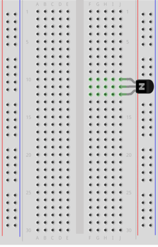
Step 1: Connect The Transistor
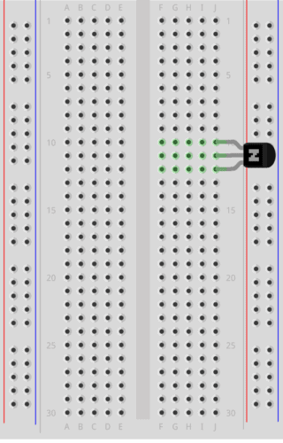
Start by connecting the transistor a little bit down on the board.
If you’re using a BC546/BC547/BC548 transistor, you can connect it as shown in the figure. The collector goes into row 10, the base in row 11, and the emitter in row 12.
Note: If you have a different transistor model (ex the 2N3904), you need to check the datasheet to find out which leg is which, and adjust your connections accordingly.
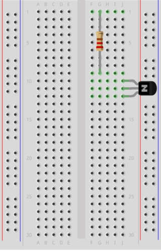
Step 2: Connect The Resistor
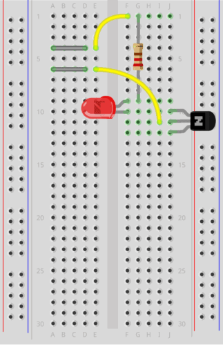
Next, connect the resistor. Connect it from row 1 to row 9.
Notice that it is not connected to the transistor since the transistor is connected in row 10.
(In the following images, a 220 Ω resistor is shown. But it could be a good idea to use a larger value like a 470 Ω resistor to make sure your LED can handle the current.)
Step 3: Place The LED And Touchpad
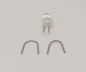
Now, you’re going to connect the LED and the touch-sensing part. For the touch-sensing part, you’ll need two exposed wires. You can get this from the LED. The LED has much longer legs than needed.
Cut off the legs of the LED so that only around 1 cm / 0.4 in is left on the LED. Bend the two legs that you just cut off, as shown below, so that they fit in between four columns on a row.
Place one on row 4 between column A and D. And one on row 6 between column A and D. This leaves room for a jumper wire to be connected later.
Insert the LED with its positive side on row 9 column F, and the other side on row 10 column F. Now the LED is connected between the resistor and the collector of the transistor, just like in the schematics of this circuit.
Step 4: Connect The Touchpad
Now you need to connect the two touch wires to the correct points in the circuit, using jumper wires.
Connect one jumper wire from row 1 column F to row 4 column E. And one jumper wire from row 6 column E to row 11 column I.
Step 5: Touch It!
Next, connect a jumper wire from row 1 column J to the positive supply column on the right. Then connect a jumper wire from row 12 column I to the negative supply column on the right.
Connect your battery connector and plug in the battery.
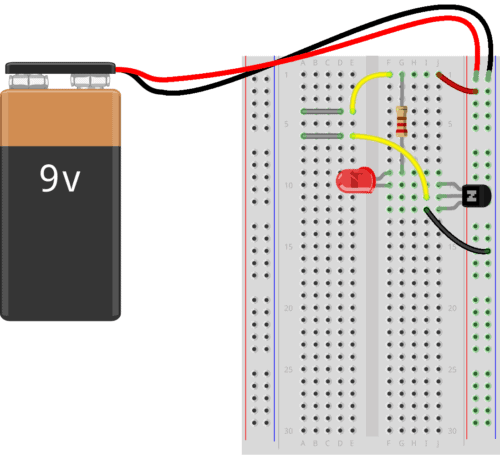
If everything is connected properly, nothing should happen right now.
But then, try to touch the touch wires so that your finger touches both wires at the same time, and the light will turn on.
If you can’t see the light, try making the tip of your finger wet before touching again. When the skin of your finger is wet, the resistance decreases so that more current can flow through your finger and to the base of the transistor.
What If There Is No Light?
In this circuit there are three common errors:
- the orientation of the LED is wrong
- the orientation of the transistor is wrong
- you are using a PNP transistor instead of an NPN transistor
- your finger is too dry
The NPN and the PNP transistors look exactly the same, so the only way to distinguish them is to look at what is written on the transistor. If it says BC557, it’s a PNP transistor, which is *not* correct. If it says BC546 (or BC547 or BC548) it’s NPN and it’s correct.
If you tried all of the above and it’s still not working, check the resistance value of your resistor. It should be 470 Ω. If it’s much more, it restricts the current to the LED too much. If it’s much less, it might have broken the LED.
If you have any questions about this experiment, use the comment field below.
The Result
In the video below you can see the process of building this, and the final result showing the working circuit:
More Circuits & Projects Tutorials

10 Simple Steps to Learn Electronics
Electronics is easy when you know what to focus on and what to ignore. Learn what "the basics" really is and how to learn it fast.

That’s more clearly even I know how to build it.
Pls explained the it wel ..I have never use vero board before so create a video on how to link components on vero board …pls that just i need for now…thanks
Veroboard is the same as a stripboard – check out this: https://www.build-electronic-circuits.com/stripboard/
Cheers!
Oyvind
It’s nearly the same as a stripboard, just a little different.
https://goo.gl/images/ALQmeh
This image shows the breadboard and the black lines show where it conducts the electricity.
good i wanna try it
If i touch a wire with my right hand and the other with my left does the LED turns on?
Exactly =)
I tried it in a breadboard but it doesn’t work .
Can u pls explain.
Hi,
It could have something to do with the LED and the resistor you use. Try a lower resistor value for R1, such as 100 Ohm.
Best Regards,
Oyvind
Sir, please explain the application &use
hello plz could u help me to build a simple touch circuit
hey buddy ty for the idea
Sir I need your help I want your email ID please mail it to me
SIR PLEASE GIVE ME ITS PLACEMENT ON PCB ,, I NEED IT BADLY
Hi thank you for your post. I would like to make a variation of your circuit to apply it to a problem I am currently working on: I want circuit A to send a signal when I switch it on by touching with my left hand, and circuit B when I touch it with my right hand. Now, those circuits have a common ground and in order to close circuit A for example I have to touch the common ground and the other branch of the circuit with my left hand. However when I tested it I detect a cross talk that I am not sure how to get rid of. Do you have any suggestions on how to make it work?
Thanks for this fun little project. Took me a while to find a transistor that could do the job, but in the end I used an old BC237 that I had laying around.
The circuit is fun as I can see the led intensity change based on the wetness of my finger, ie how the base current controls the collector to emittor current.
In your other transistor tutorial you use a battery to supply current to the base to turn the led on and off which makes sense to me. However I am still confused about how your finger is supplying the current. Is it because you are completing a seperate path for the electrons to flow from negative to positive? Thank you!
The current flows through my finger from plus to minus. Without the finger, there’s no path for the current to flow through the base. The finger acts as a resistor, allowing some current to flow from plus, through the finger, through the base and down to minus/gnd.
Sir, where to apply this
Which type of touch sensor is this ….?
I did experiment..Not working…which wires , we have to use as touch wires
Any wire where the bare metal is exposed should work.