Do you want to build a circuit that blinks a light? This inverter-based circuit is simple, and it’s small enough to fit on a breadboard.
The circuit uses standard basic electronic components and you can build it even if you have never built anything before. Check out the full build instructions in the video below:
Scroll down to find the complete circuit diagram, component list, and step-by-step instructions (in text-form) on how to build this circuit.
The Circuit Diagram
In the lessons, you learned that you needed an inverter for this circuit. But there’s one important point if you want to build this:
You need to use a Schmitt-triggered inverter. It’s an inverter where the voltage at which it switches from LOW to HIGH is higher than the voltage for switching from HIGH to LOW.
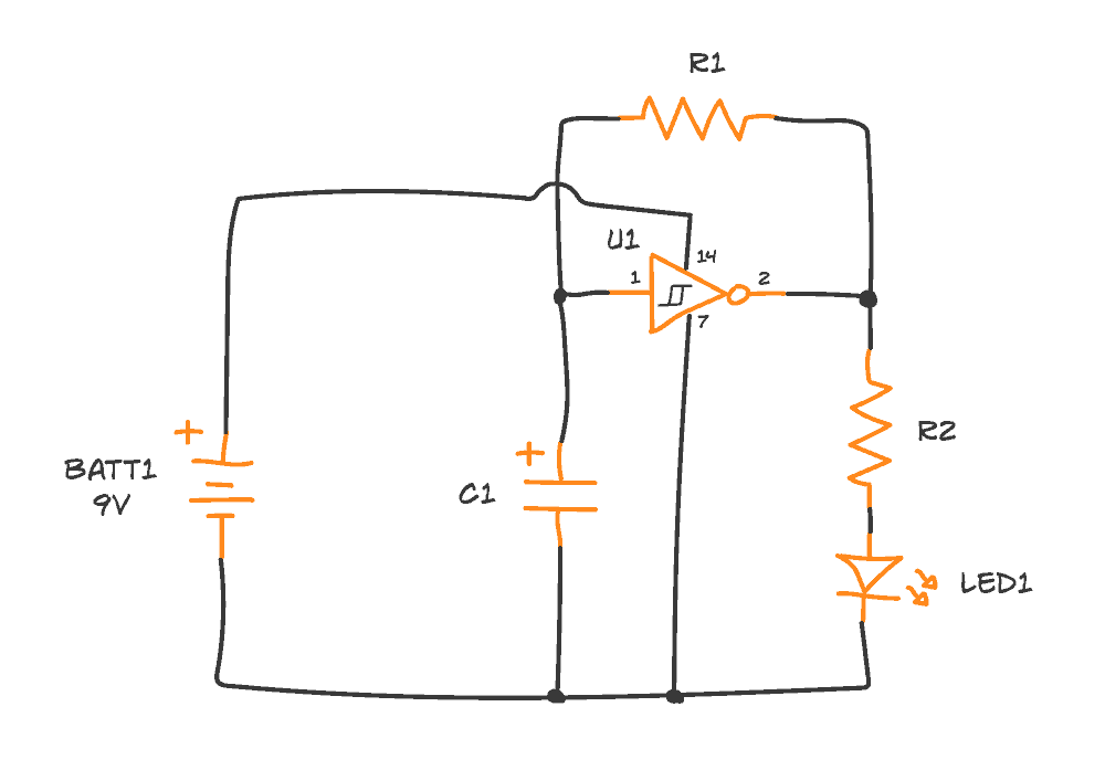
You’ll find the complete circuit diagram below.
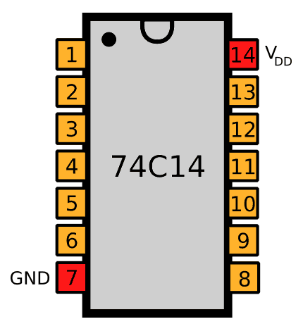
The numbers next to each pin in the diagram represent the pin number on the integrated circuit. Click here for the pinout of the Hex Schmitt Trigger Inverter IC.
The Components You Need
| Part | Value | Note |
|---|---|---|
| – | Breadboard | Breadboard |
| – | Jumper Wires | Any stiff wire (22-23 AWG) |
| – | 9V Battery clip | To connect the battery to the board |
| BATT1 | 9V Battery | To power the circuit |
| U1 | 74C14 or CD40106 | Hex Schmitt Trigger Inverter |
| C1 | 100μF | Polarized capacitor |
| R1 | 10 kΩ | Any resistor type |
| R2 | 10 kΩ | Any resistor type |
| LED1 | Red | Standard LED (low power) |
These are pretty standard components that you can get from most places that sell parts for building electronics. I’ve created a page with a list of where to buy electronic components here. They’re also included in the Ohmify Beginner’s kit (except the battery).
10 Simple Steps to Learn Electronics
Electronics is easy when you know what to focus on and what to ignore. Learn what "the basics" really is and how to learn it fast.
Build The Circuit Step-by-Step
When you have the components in hand, you’re ready to build the circuit.
Not sure how the breadboard works? Then you might want to read How To Use a Breadboard first.
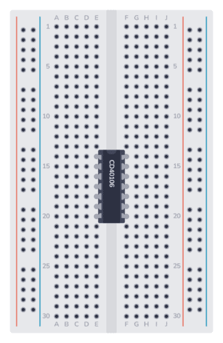
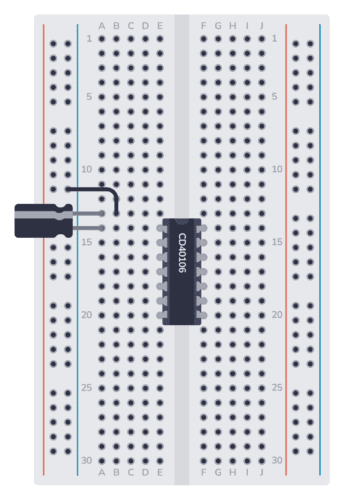
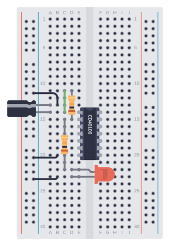
Step 1: Place the Integrated Circuit
Start with U1, the Hex Schmitt Trigger Inverter IC. Place it across the gap in the middle, with pin 1 in the upper left corner.
Step 2: Place the Capacitor (C1)
Next, place the capacitor C1. First, find the negative pin. It should be marked with a minus or zero. Often the negative pin is shorter than the positive pin. Connect the negative pin to the negative supply column (either directly or using a wire). And connect the positive pin to the same row as Pin 1 of the IC.
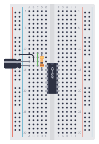
Step 3: Place the Resistor (R1)
Connect resistor R1. It should go from the input (Pin 1) to the output (Pin 2). Bend the legs of the resistor so that you can connect it from the row of Pin 1 to the row of Pin 2, or connect one side to an empty row and use a wire.
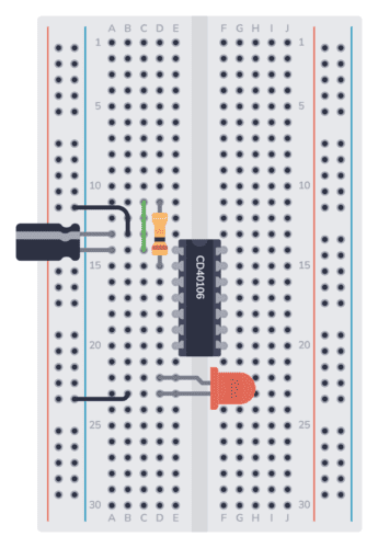
Step 4: Place the LED
Next, connect the LED. The negative leg of the LED is the shortest one. Connect it to the negative supply column (directly or using a wire). Connect the longer leg to an empty row.
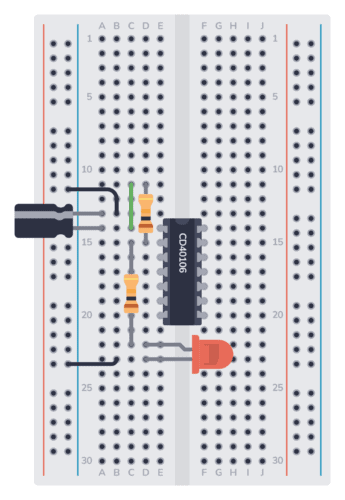
Step 5: Place the Resistor (R2)
The resistor R2 connects the output (Pin 2) to the LED. Place one leg of the resistor into the row of Pin 2. Place the other leg on the same row as the long leg of the LED.
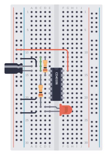
Step 6: Connect GND to Minus
The GND (Pin 7) of the IC must be connected to ground. In this circuit, ground is the minus of the battery. Connect one end of a jumper wire to the same row as Pin 7. Connect the other end to the negative supply column.
Step 7: Connect VDD to Plus
The VDD (Pin 14) of the IC must be connected to the positive supply. Connect one end of a jumper wire to the positive supply column. Connect the other end to the same row as Pin 14.
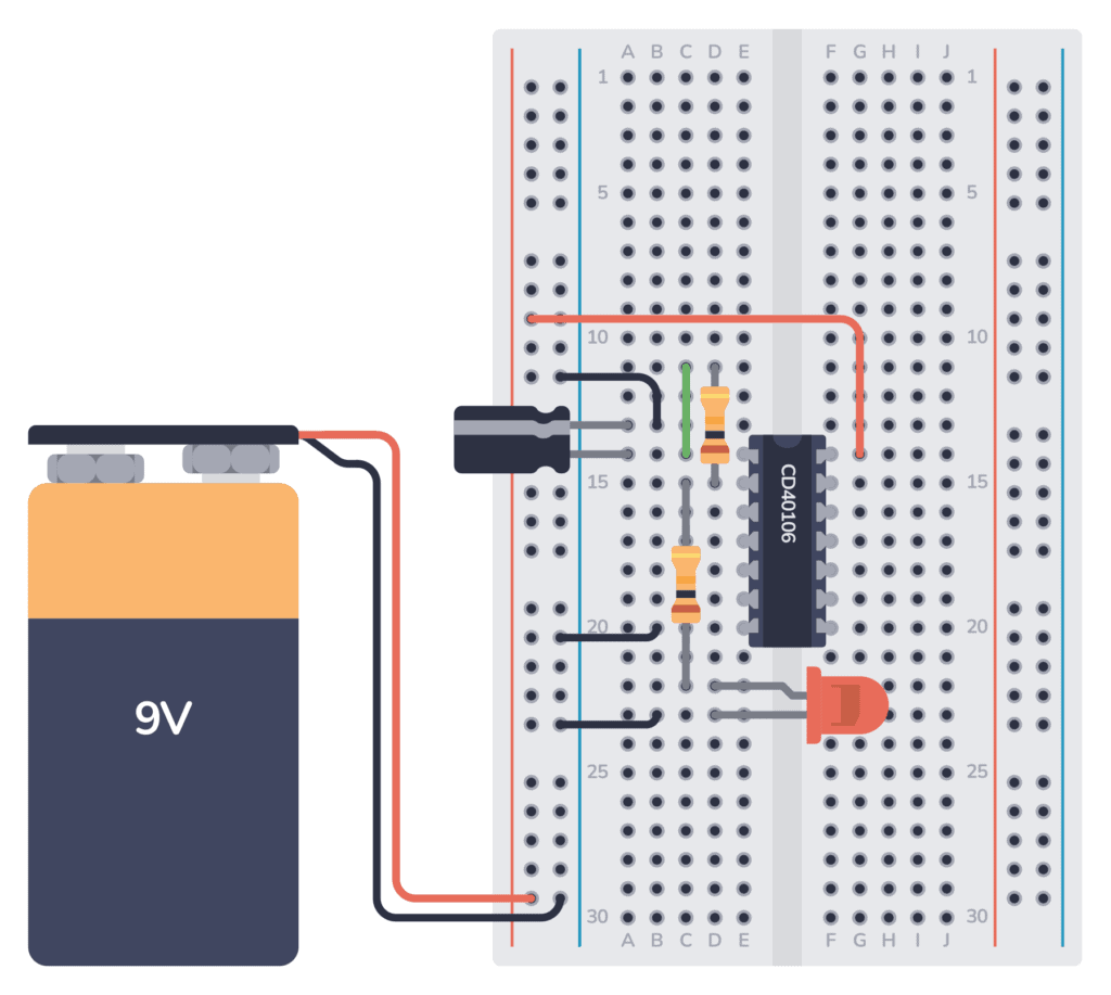
Step 8: Connect the Battery
Finally, connect the red wire from the battery to the positive supply column. And connect the black wire to the negative supply column.
Your LED should start to blink.
Questions?
Did you build it? How did it go?
Let me know in the comments below.
More Circuits & Projects Tutorials
Build Something Useful This Evening
This gadget lets you use any IR remote-control to control your lamp, garden lights, heater oven, garage door, or anything else.
Hi
I’m looking to build a Star Trek TNG TRICORDER light and sounds,
But I’m not sure how to do it. Any information you could share, would be much appreciated. Or where I could find that information. They used to sell them on eBay, but I cannot find any.
still struggling with the blinking light. My energy source is a solar light for area lighting with a 3.7 volt Li-ion 800 mAh rechargeable battery. it’s currently reading 2.11 volts. I’m not sure on the pin outs of the inverter. Actually I would love a pin out on the schematic.
7404 is the original TTL chip, look it up by searching on 7404 datasheet, in fact you can search on anything that way, 74c04 data sheet.
But pin 1 = input to first inverter, pin 2 = output of 1st inverter, the 74C04/7404, etc is a six inverter IC pin 7 = return/ground, pin 14 = Positive Voltage power source. For TTL 7404 that 4.75 – 5.25 volts, for 74C04 we know it’s at least up to 9V.
Inverter input pins
1
3
5
—-7 = Gnd
8
10
12
—-14 = + power input
Inverter output pins
2
4
6
—-7 = Gnd
9
11
13
—-14 = + power input
it is very interested thank you so much.
How did know this?
Great information. I’m looking to have a LED blink but I want the LED to slowly light and then slowly go off. In a two second cycle loop. Any suggestions?
Maybe use a adruino board?
U can use a dimmer led instead but that will blink rapidly and slowly light off
It is quite good and easy to follow .I do not know if the mismatch happens
Yes I have a Comment why don’t you build it step by step show how to build it not just to show it light up ?
I just updated the article with step by step instructions. Hope you’ll find it useful!
OK, list the parts and where I can get them. I would have loved this sixty years ago but right now I want to finish my prioject AND I do see future projects that wil required me to dig a bit deeper.
Hi Bruce,
Here’s a page with several options on where to buy the components from:
https://www.build-electronic-circuits.com/buy-electronic-components/
Best,
Oyvind
Hi,
I want to make 3v LED Flash light with LDR.
This type of light is using fishing purpose in sea.
Regards
Niladri
I am still unsure about how the voltage interacts with the inverter. If I track the current, it leaves the positive pole of the 9V and travels directly to the inverter (at the input labelled 14). I assumed that this was the power supply to the inverter and would be constant. And that this voltage would exit through the output labelled ‘7’ and return to the battery. Is this an activating voltage that would then cause the inverter (with no initial voltage at the input labelled ‘1’) to output a voltage at ‘2’, which would loop around and cause the inverter to switch, initiating the on/off loop? Sorry if this is confusing…
The pins 14 and 7 are for powering the inverter. When the output is HIGH, it’s from here the output gets its voltage and current, yes.
OK…update. I triple checked the schematic and used a couple of combinations. First I used a 9 Volt battery with the solar light and later on LED and in both setups I got a strong resulting illumination. I then used the solar panel with the 2.1 volts with both LET setups and got a average illumination result. The appears to be a slight flickering of the lights but it is very low and fast. Hard to detect at first. What is next?
Bruce
Check out the datasheet for the chip:
https://www.mouser.com/ds/2/308/mm74c14-1193355.pdf
From there you can see that the chip needs at least 3V. So 2.1 will probably give unreliable results.
I appreciate your response and that makes sense regarding the voltage level but I had the same results when I substituted a nine volt battery as the power source. My power source is a yard light that comes on at night and goes off during day light hours. The light works fine in the constantly on position but I can’t get the slow on and off that I need for my project. Any suggestions as to possible substitution?
Are you saying that your circuit is not blinking when you use a 9V battery? One potential error is that the LED draws too much current. Try replacing the resistor in series with the LED with 2000 ohms.
If it’s still not working, measure the battery voltage when it’s connected to the circuit. If it’s less than 9V, you might have a battery that is almost dead. Try replacing with a new one.
new 9 v battery. I really need to get this to work with the solar panel so the batteries will recharge. the rechargeable batteries are 3.7 V. back to the drawing board.
So basically for this project to work as designed I need to use the solar panel (Wal Mart outdoor light) Which is powered by a 3.7 Li-ion battery. There’s lots of sunlight in south Mississippi. Will that work with your design?
The circuit in this article should work fine with voltages above 3V. But you might need to adjust the resistor for the LED.
It Works but it is blinking a little too fast. What rate resistor do I need to use instead of the 470?
It’s the 10k resistor or the capacitor you need to change to change the speed. You can for example try doubling the resistor value to 20k.
The 470 resistor sets the brightness of the LED.
hi Oyvind,
I notice in your “Basic Electronic Components” ebook you provide a schematic for a Blinking LED using a 555 Timer IC. Can you compare and contrast the pro’s and con’s of building it that way, compared to the way you show here in this article please?
thanks
– Garry
The inverter uses less components. But other than that, for blinking an LED they’re pretty much the same.
A step by step assembly video or series of drawings would certainly help this old person. I find it difficult to tell where to hook the components up on the breadboard.
FYI: I hope to use a modified version of this circuit to drive five LEDs on the rear pair of arms on my first quadcopter.
Hey Robert, I just updated the article with step by step instructions. Hope you’ll find it useful!
The video is not there for me.
It’s a youtube video. And it’s there. Maybe you’re on a network that blocks youtube?
With all due respect, nowhere do you explain the THEORY OF OPERATION of this circuit! Without this, how can a novice possibly understand HOW and WHY it works?!
I’m a long time electronics hobbyist, so it’s no problem for me. But I’m quite amazed at the absence of an EXPLANATION in what is supposed to be a LEARNING thing.
This is how to build it. The lessons on how it works can be found here: https://www.build-electronic-circuits.com/free-email-course/
Would the LED still blink if I eliminated the inverter and worked with only the battery, capacitor and resistors?
No. The inverter is the key to the blinking.
I don’t have a cd40106 or a 74c14. I do have a 74ls14 but even with a new battery the led just lights for a moment and then goes out. If I remove and reconnect the battery the light lights for a second and then goes out.
Is it possible the LS version of the 74 14 is not compatible?
thanks.
The 74LS14 will only work with a 5V power supply, not 9V. If you switch to a 5V power supply instead of the 9V battery it should work. You might need to reduce the resistor value for the LED a bit.
My light came on but did not blink. Only after I put in a different converter of the same type did it work. Maybe a faulty component? How robust are they? I had to squash the legs to get the inverter onto the breadboard. Took me a bit time to get it to work but it did eventually !
They are pretty robust. But you can break them if you connect to a higher Vcc voltage than they are rated for. Ex the 74LS14 only works with 5V, while the 74C14 works with up to 15V.
A typical error is connecting the chip upside down.
It was great to see the light blink. It looked like the capacitor was in parallel so I pulled
it out of the circuit and the light went steady. I am enjoying your course and look forward to learning as I grow older. I figure electronics will keep my brain healthy. I ran across an old gentleman back in 1960 who had a mantra he lived by; Sinesco Disens ( I grow old learning.) I think he is right.
Chuck Lowe
That’s great to hear, Chuck! And there’s always more to learn in electronics =)
Correction: He stays young learning!
My first circuit! Eureka, a blinking light. Great lessons. Thanks Øyvind.
Nice! Congrats!
Hi there,
I find your circuit very easy and straightforward. I found another method of slow blinking/blinking led circuit. Using BC 547, 100μF, 555 timer and some resistors.
My question to you is, could you help me out to design a circuit to fit in 40 LED with a function of slow blinking?
Success! I assembled the components per the tutorial, and it worked the first time.
The battery connector that came with my kit has a barrel type connector on the end, versus red and black wired pins, but that can be worked around. What I’d like to know is how to insert a button switch (4 prong) with a button into the circuit so I can turn it on and off easily. First electronic project I have ever done.
Congratulations!
To add a button you can move the long red wire that goes to the upper right corner of the chip. Have that red wire go to one side of your switch instead, and connect a wire from the other side of the switch down to the upper right corner where the red wire was connected before.
Best,
Oyvind
Can you please explain the working
You can learn it through the free email course: https://www.build-electronic-circuits.com/free-email-course/
What does these initials stand for
GND
VDD
It’s the negative (GND) and positive (VCC) voltage connections.
Using a SN74LVC2G14DCKR, powering with a 3.3v supply to mimic dev board vcc, same circuit. Using a 50 Ohm resistor on the led but can’t figure out the R1 and Cap. I’ve tried many but the led keeps blinking too fast. I’m not grasping the logic of how I should alter the values to slow down the cycle.
Hi Sam, the higher values you choose for R1 and the cap, the slower the LED will blink. If you are using 100 µF now, try with 1000µF.
this is the blinking light circuit I build this. cool and neat to build the circuit
I am unable to get the IC 74C14 from the market. But I did find IC 74HC14N, but LED is not going to ON or blinking
It should work, but note that the 74HC14 only supports a power supply of 2V to 6V. If you connected 9V you might have broken the chip.
I think for teaching beginners about blinking a light, the relay method is better than this.
The ‘Hex Schmitt Trigger Inverter IC’ is hard to find both online and offline. (I didn’t try offline. )
You’ll find it as 40106 or 74xx14 (where xx can a number of different letters)
Hi Oyvind, just tried the circuit, I’m using the sn74sl14n, the led just stays on I’m using the 10k on pins 1 and 2 with a 1k from pin 2 to the led, and using 5 volt power supply.
Hi Lawrence. The sn74ls14n only supports up to 0.4mA output current when output is high. Since you are using a 1k resistor for the LED, you would need 2-3mA to turn on the LED.
The simplest solution to this is to use a 10k resistor instead of the 1k resistor. This will only work if your LED lights up with only around 0.3mA, but many LEDs will work.
I have just built the flashing led using the Schmitz trigger. It works fine but the led is quite dim.
Great! And yes, the LED will be dim because of R2. 10k is quite high for an LED. You can try with 1k – although depending on which schmitt trigger chip you have it might or might not work. If you have 74C14 it will work. If you have cd40106 it might not work.
The “best” solution is to add a transistor as a switch to turn on and off the LED – then you can have it as bright as you’d like.
Thank you
Hi,
Tried building the circuit in Tinkercad (I don’t have the inverter yet) but it’s not working.
Could you maybe have a look at it? I can’t find what I did wrong…
https://www.tinkercad.com/things/kdtHfpGMp3r-powerful-trug/editel?sharecode=n5-AFg6EjbR35YzR_qdvH61AsksPEz2fXSrFzwzWGyY
Same question, did you get any solution to that problem?
The link has expired so I can’t see it…
Thanks sir for making electronics simple..
I want your help..
In this circuits I used 555 timer to blink..
It works…
Then make alternate blinking with 2 leds.
Then make dual alternate blinking all works great…
..
So I want make finally to blink four leds with different times..
I connect capacitor and resistor by calculating time constant one of those led at one transistor and one at the sides of another transistor…
It doesn’t work…
What’s wrong…
Please describe..
Hard to say without seeing the circuit. But one thing to check is if the current you’re pulling for your LEDs is higher than the current the 555 timer can provide.
I finished the blinking LED well it was weak and slow. My son took a look and played with the resistors for pulse rate we used 2.7-22K and 680K for light intensity way better . PS HE HAS DEGREE IN ELECTRONIC.
Great! I assume you mean 680 Ω (without the k). The only thing to be aware of is that the CD40106 can only provide around 1-2 mA of current. The lower you go with the resistor for light intensity, the more current you’ll pull out if it.
I have been a Ham Radio Operator for many years but have not had much interest in IC Technologies until this. I have always built equipment. This is new learning and a lot of fun. YOU CAN TEACH AN OLD DOG NEW TRICKS!
Gray
I’m not an expert in circuit design or analysis, and I’m always learning. I received this circuit discussion in the email tutorial that came with signing up to download your KiCAD guide – a helpful starting point. If the email course hadn’t been a product of the guide, I wouldn’t have looked at it.
After following the tutorial segment I got each day, it occurred to me that my learning has always been discouraged when ‘magic’ was presented and never adequately explained. Yes, the magic inspires me to dig deeper, but understanding IC magic often requires further explanation by an experienced user. For example, finding, reading, and understanding the important parts of an IC data sheet is not a skill we’re born with. Even though I’ve looked at many IC data sheets, I’d still appreciate having an expert walk me through one with the opportunity to ask questions.
The email tutorial was an intro course to basic components, but including the IC with less explanation than that given for the resistor or the capacitor was discouraging to me. I like how you described the simpler/basic electronic components in everyday terms that most people can understand. It appears your dad was a good teacher, and you were a good student.
Keep it up!
Hi Greg,
Thanks for your feedback!
Hi Oyvind !.
Thanks and the circuit is working so nicely.
Best regards,
Great to hear!
It didn’t work at first. I hadn’t seated the inverter all the way. Now it works fine! Thanks for the instruction.
First I would like to thank you for this course. I had zero knowledge of electronics coming into it and now I have a base to continue on learning.
Long story short I have a LED in my boats bathroom that lights up when the holding tank is nearly full. The float in the tank is the switch. My question is can I use all the components listed here on a 12 V system or should I start at the LED and work backwards to find what voltage I need at each point and use appropriate components ?
Hi Bob,
For this circuit, you need to make sure the inverter chip can handle 12V. You can do that by checking the datasheet of the chip. If you are using 74C14
or CD40106, both of these chips support 15V or more, so it will work fine with 12V.
Mr.Oyvind I have really enjoyed your lessons so far,I have also tried step by step building simple circuit of LED blinking which is very much successful keep up bro.
Hello. Is a capacitor like this likely to blow if powered in reversed polarity? I have seen some videos on the web where they go off pretty badly and I don’t want to make the same mistake.
Not if you’re using a small 9V battery. It might get damaged and loose performance or even stop working, but blowing up – not so likely.
HI, I managed to get it working.
What are the main uses of the Schmitt trigger & where do you suggest going from here regarding circuits that use the IC?
Great! In the hobbyist community is probably most used to make oscillators. You could try continue by connecting a buzzer/speaker and increasing the frequency so that you get sound.
Well I managed to cook my chip!
Having read the data sheet for the chip I used I found out why, max 7 volts (I have learnt something check the data sheet)
I am using a Bojack SN74HC14N running on 5 volts but the led does not blink do I need to use different resistors or capacitor.
I do have a ohmnify subscription and will be receiving a correct chip. Very curious as how to fix this circuit at low voltage
I have finally found a solution that works for this chip, I am a newbie but I used a 100k resistor with a 100up capacitor for the blink time and a 100R resistor for the LED, the main reason the SN74HC14N did not work was because you need to link all the unused inputs back to VCC which in my case was 5 volts from a small power supply
I did a lot of web surfing to find a likely solution and I thank Thomas Kim for a YouTube video which put me on the right track.
There is a saying No Pain No Gain, I am finding that components vary so much it’s difficult when you cannot get the same part as the teacher, but I also think if you are prepared to do some homework you get a lot of satisfaction when you succeed.
Hey Dennis, glad you figured it out! Also, if you ever need help, you can use our member-only forum (under Community when you log in at Ohmify). The team and I are there answering questions every day.
I built my first circuit! Thank you very much! I ordered the components from SparkFun. For me it was easier to find what I was looking for then some other sites. Anyway, it worked just fine when I finished building it but I don’t quite understand the flow of current and how it interacts with the capacitor and inverter. So, I’ve signed up for the free email course as I see others had similar questions. I’m excited! Again, than you very much!
That’s great to hear!
I recently constructed a flashing LED using the Schmitz trigger. Although it functions properly, the LED’s brightness is relatively low.
That’s because R2 is very high. A quick fix is to reduce R2 value. But if you reduce it to much, you pull too much current out of the chip, and it will malfunction.
The solution is to add a transistor to the output and let the LED be powered from the transistor. Here’s more on howto use a transistor: https://www.build-electronic-circuits.com/how-transistors-work/
Thanks for this tutorial! I built my first circuit! But something strange is happening…
The LED is blinking, but only when the jumper cable from the negative supply column is connected to pin 6 of the inverter (or any other middle pin) and not pin 7. I mistakenly connected the cable to pin 6, and when I realized it was in the wrong row, I changed it, but it stopped working!
I would send a picture if I could to show you proof of this strange occurence. Do you know what is causing this?
Many thanks!
Thank you very much for this reply, this solved my problem. I found that moving my connection from pin 7 to ground and putting it instead in pin 6 to ground it fixed it. No idea why this is happening, but would love some insight!
I am working with 9v battery, CD40106B inverter and all the same other components as mentioned in the video.
Pin 7, ground, needs to be connected. If it’s not connected and it’s still working, that’s weird. Sure you haven’t connected the chip upside down?
Hi, that’s definitely strange. But hard to debug the problem from afar…. I would start by checking that you’ve oriented the chip the right way and that you’re using the correct chip.
Why is the 7414 referred to as u1 , what does that mean ?
Thanks for this, I copied out the schematic in easyEDA and I’ll simulate it in the CRUMB app :) , Will test it physically at some point when I get a breadboard and other components .