In this Halloween electronics project, I’ll show you how to make a cool Jack-O-Lantern. I used a 3D-printed carved pumpkin, but a real one works just as well (or even better!).

The project is based around three normal LEDs that I control so that they look like a flickering flame. Since my “pumpkin” was very small, I used 3mm LEDs. For bigger pumpkins, I recommend using bigger and brighter LEDs. For example these ultra-bright orange LEDs.
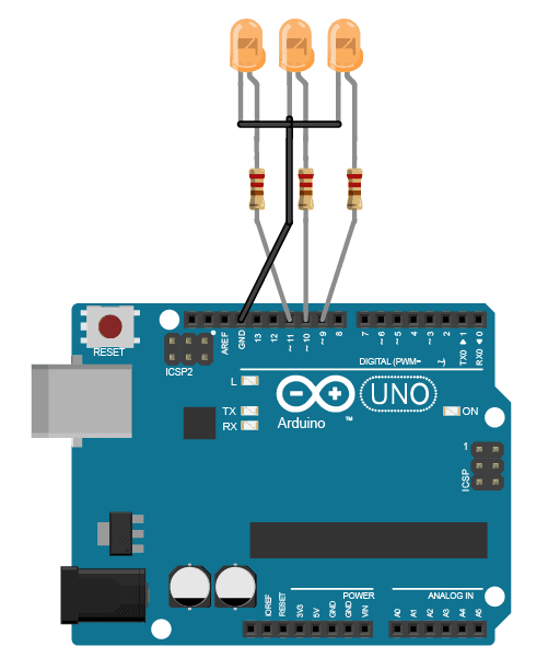
The LEDs are connected in series with a resistor to the PWM pins on the Arduino so that I can control the brightness. And in the code, I change the brightness of each LED to a random value for every 50 milliseconds.
The result? Check out the video below:
Jack-O-Lantern Connection Diagram
Components Needed
- 3 x LED (Orange)
- 3 x Resistor (220 Ω)
- Arduino Uno
- Carved pumpkin (or something else to place the LEDs in)
I 3D-printed this pumpkin model from Thingiverse, but you can place your LEDs in whatever you have at hand. A carved pumpkin? A mummy jar (by wrapping some bandage around a jar and adding eyes)? Or an old /spooky lantern.
Preparing the LEDs
Start by bending the positive leg (the longest one) of each LED:

Join the three negative legs and solder them:

Solder a resistor to each of the positive legs:

10 Simple Steps to Learn Electronics
Electronics is easy when you know what to focus on and what to ignore. Learn what "the basics" really is and how to learn it fast.

Solder wires for connecting to the Arduino, then cover with shrink tube:

Connect the negative wire to GND on your Arduino and the positive legs to pins 9, 10, and 11 on the Arduino:

Code for Flickering LEDs
The code is pretty straightforward. In the setup() function, I set up the LED pins as outputs. And in the loop() function, I use the analogWrite() function to set a random brightness value to each LED, with a 50-millisecond delay between each change of value.
// Halloween Project: Jack-O-Lantern with flickering LEDs
// Code by Oyvind Dahl
// www.build-electronic-circuits.com

int ledPin1 = 9;
int ledPin2 = 10;
int ledPin3 = 11;

void setup() {
  // Set LED pins as outputs
  pinMode(ledPin1, OUTPUT);
  pinMode(ledPin2, OUTPUT);
  pinMode(ledPin3, OUTPUT);
}

void loop() {
    analogWrite(ledPin1, random(10, 255));
    delay(50);
    analogWrite(ledPin2, random(10, 255));
    delay(50);
    analogWrite(ledPin3, random(10, 255));
    delay(50);
}
Questions about this Jack-O-Lantern project?
Let me know your questions about this Jack-O-Lantern project in the comment section below!
More Circuits & Projects Tutorials

Build Something Practical This Evening
Download this tutorial that shows you step by step how to build an old-school USB charger for your mobile.
I like this a lot! I was wondering if there was a way to make a flickering LED circuit without the arduino?
Thanks! Yes it is. For example using the ATtiny85 microcontroller. Basically any microcontroller would be able to do this.
If you’re interested in doing it without a microcontroller, it’s a bit harder. You’d need some way of creating a (seemingly) random voltage. My first thought would be to use a shift register with some initial values in a loop somehow. Then use the output of this into a DAC circuit.
But this quickly becomes a large circuit. There might be a smarter way to do it that I am not thinking of right now.
Ha yes i thought it would probably get a bit more complicated! I will look into what you mentioned, altho i think i’ve missed the halloween boat but i was planning to use in a xmas decoration too. Many thanks!
What’s the main reason for chosen the Pin 9-11
,But not other random pin like 3-5-6
Also can u explain to me what is Int, Void loop, Void setup in your coding.
https://www.arduino.cc/reference/en/language/variables/data-types/int/
Int is integers, or a set value. You set a pin to equal a number value that the Arduino can adjust output to.
Void loop is the loop of code that will read over and over and over until some other instruction is triggered. Such as, if you have two pins set as inputs, and put and IF statement for each. I have a sketch that has a series of 12 lights just do a chase light pattern (Christmas lights) as the default loop. IF pin one goes high (power to that pin through a switch), then only the first light goes on (ready indicator). Then IF pin two input goes High (single push, single throw button), then the sketch does a count with 500 delay, so it works as a one minute count down timer, then holds at the ready indicator state again.
All sketches are a loop, but you can set up loops within loops, as well as loops to trigger outside of the other loops.
VOID SETUP is where you do your setup, telling the Arduino what inputs you will be using and what they will be doing – input, output, meter, etc. It is like the BIOS of your sketch, telling each pin that it is a pin and not a paperweight…
Hope this helps.
Using a MP is a great way to do it and some interesting projects can be done with them. Sometimes it may be just a convenient to use the ‘old fashioned’ ICs to get the job done without them.
To get a ‘flickering’ output you can use the outputs of a 4015 shift register and 4093 Schmitt-triggered NAND gates to provide the clocking inputs. Wire as indicated below using a 9vdc power supply with the 4015 Pin 8 to Ground and Pin 16 to +9 : on the 4093 Pin 7 to Ground, Pin 14 to +9. The LEDs can all be of one color or variable colors, your choice.
Draw out the instructions below for easier completion.
[1] Connect Pin 1 of the 4093 to output Pin 5 of the 4015 and Pin 2 of the 4093 to output Pin 12 of the 4015.
[2] Connect Pin 3 of the 4093 to the ‘serial input’ Pin 7 of the 4015. On the 4015 connect Pins 1&9 together, Pins 6&14 together and Pin 10 to Pin 15.
[3] Connect Pins 5&6 of the 4093 together with a 1uf Capacitor to Ground and connect a Variable Resistor [100k ohms] from output Pin 4 to Pins 5&6 and also connect output Pin 4 to both input Pins 1&9, the ‘clock inputs’ to the 4015.
[4] Connect Pins 6&14 on the 4015 to Ground.
[5] With three or four LEDs [your choice of color] wire the Anodes of each to the 4015 output Pins 3, 4, 11, 13 and connect their four Cathode LED outputs to a single 470 ohm Resister to Ground.
[6] On the 4093 connect Pins 8, 9, 12, 13 together and then connect to Ground.
That’s about it. If using a different power supply, 12vdc for example, just increase the 470 ohm resistor to about 1k-2.2k. This is a self-operating circuit and the ‘flickering’ rate depends on the ‘variable resistor’ setting. You can use three or four LEDs with variable colors if desired.
Many thanks. I have started printing 2 X scale.
Intend to put in more LEDs into Uno pins 3 5 7.
Good idea!
Thanks for this project! My son and I put this together and he’s excited to use it tonight.
Glad to hear =)
Nice! I like the idea. Wondering if this could be set for 2 LED’s ?
I made circuits to work on 3VDC and flash the LED’s then put then in styrofoam skulls. They are small and the circuit board plus the battery case fit snugly inside. The random blink and
varying light level would be a nice tweak to this. Thinking I could use a metro mini, not sure of getting 9VDC in there though.